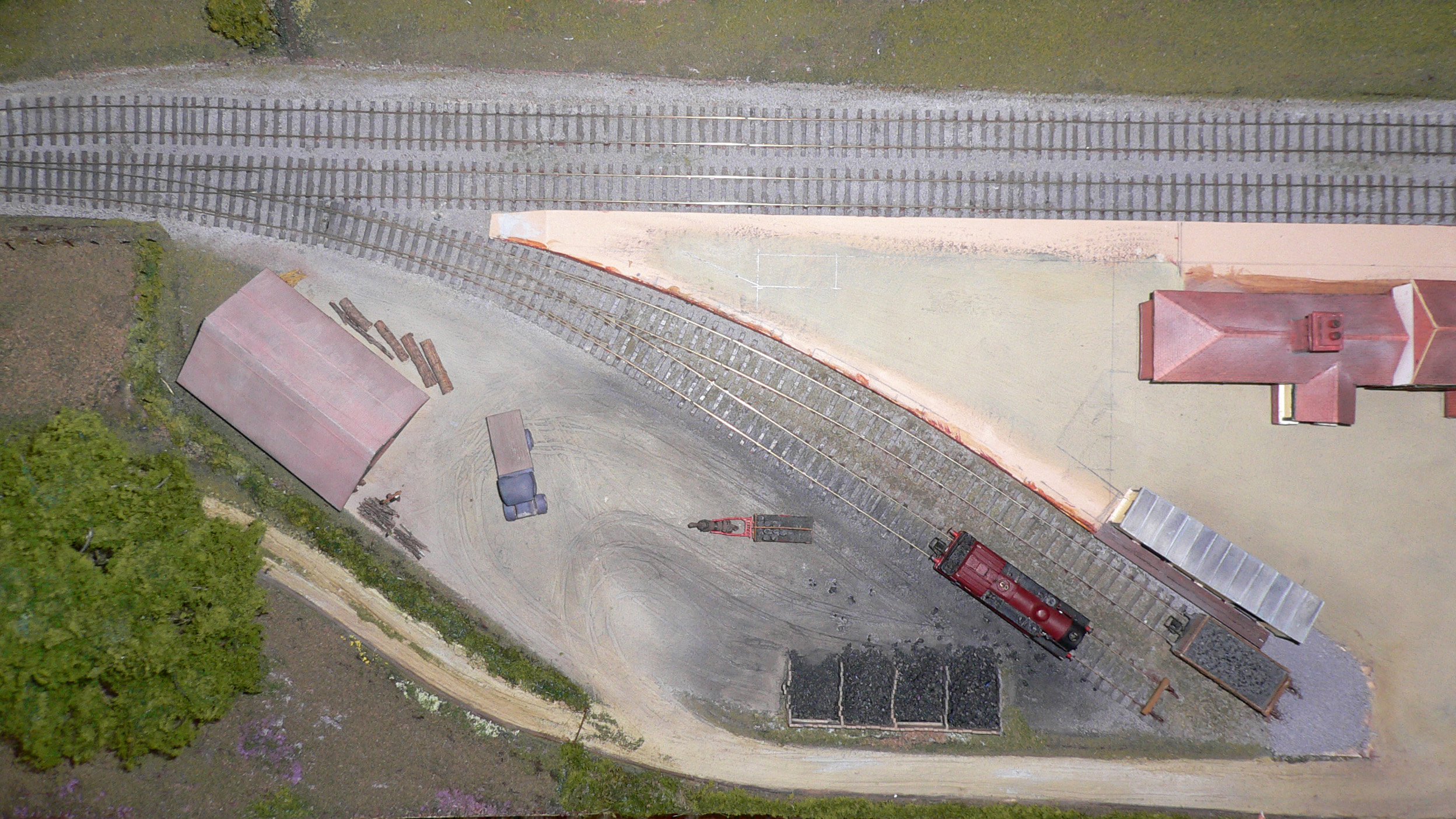
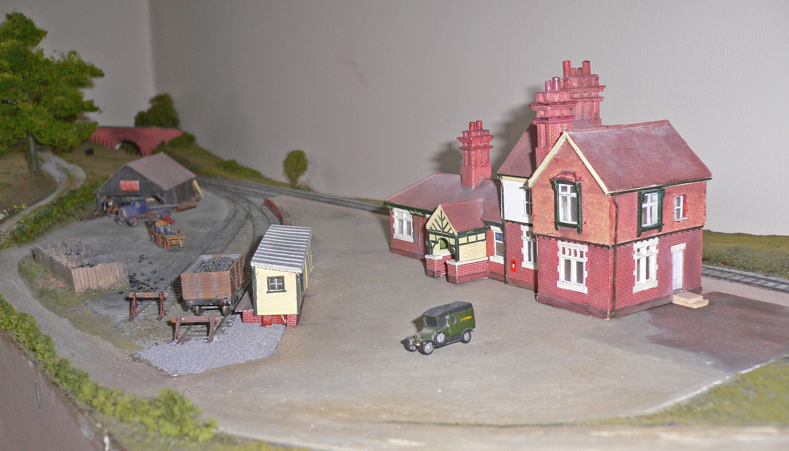
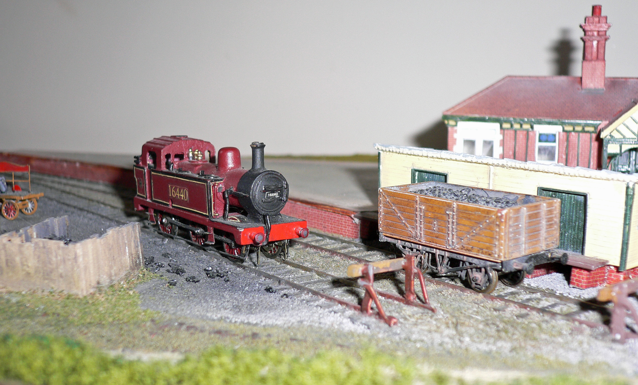
Thought you might be interested in how the station area looks now.
6 May 2009
1 May 2009
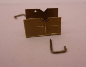
Bodger's quartering tool
I'm always looking for rough-and-ready ways of getting things done, often so rough that I end up having to do it all again, but this one worked well. It's only any good for locos with identical spoked wheels on all axles.
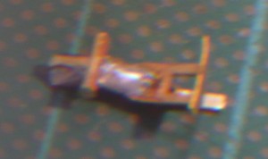
All that's needed is a bit of brass sheet thin enough to slide between the outside face of the chassis and the back of the wheels when the back-to-back is set correctly. Bend the sheet into a rough U shape as in the photo, file a couple of notches in the 'wings', then assemble the wheels on a muff in the chassis and wriggle the wings up behind the wheels so that the notches fit under the axles. Turn the left-side wheel until the crankpin is facing downwards and drill a hole through the wing in the gap beween the spokes adjacent to the crankpin. Push a bit of brass wire through the hole so that the wheel can't rotate. Obviously the wire needs to be a tight fit between the spokes and in the hole. Now rotate the other wheel until its crankpin is at 90 degrees (ish) to the first one, and drill a hole between two spokes on that side. Pop a pin in and make sure both wheels are locked in position.
Remove the pins and the tool, and you now have a template for positioning the wheels on the other axles. I found that the coupling rods dropped onto the crankpins first time, and only a hairsbreadth of adjustment was needed to relieve a minute tight spot.
The tool is a throw-away but it only takes fifteen minutes to make, involves no measuring or marking-out and costs nothing.
28 April 2009
Converting the Terrier to Finescale
At our group meeting on Saturday Nigel kindly turned the wheels of the Terrier down to finescale standards.
There wasn't much to come off but the result is certainly worth it.
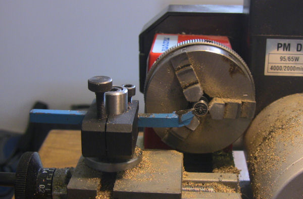
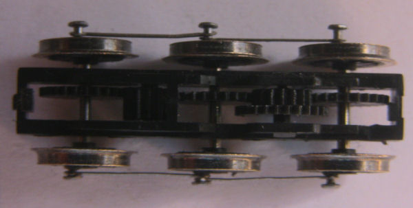
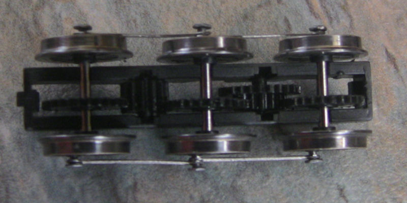
You can see from the above picture how flimsy the Dapol coupling rods are! The chassis is fully geared so the rods just go along for the ride which was lucky because the Dapol wheels slipped on their axles during the above process and needed re-quartering. In this case it is sufficient to get them close enough.
As well as straightening the coupling rods (again) I also need to reduce the height of the crank pins on one side which you will see refused to go in to the wheel as much as they did on the other side. Getting the pins in was difficult until Guy showed me a trick for holding small items using double sided tape stuck to the end of a pointed object.
When set to 9.42mm gauge the wheels just foul the plastic brake rods which will need to be filed, but only a little as they do a good job of keeping the wheels central without having to add any washers.
It looks as if the body will escape without any surgery. I have reassembled the chassis and found it impossible so far to get the front pickups in contact with the wheels - it is necessary to spring them out of the way when re-fitting the wheels and this is enough to make them lose contact. I will have to think about this...
I have also added a chip (CT DCX74z) which, although it replaced the resistor board, now intrudes quite noticeably into the cab. I may have a go at re-soldering the wires to the motor in a neater fashion which may save me a bit of space.
22 April 2009
Dismantling the Dapol Terrier - Updated
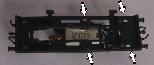
I've been asked how I got the Dapol Terrier to pieces and as it is easier to explain these things in pictures I thought I would put a few here:
1. The body is separated from the underframe by releasing four clips on the underside of the footplate.
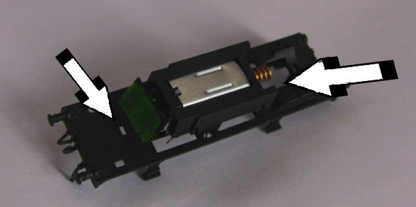
2. The footplate is connected to the rest of the underframe by (1) a clip underneath the resistor board and (2) two clips either side of the worm gear. Unclip the first from above then gently splay out the footplate near the worm gear to release the others.
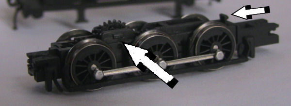
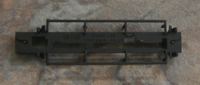
The clips that hold the underframe to the footplate. There is another clip on the other side of the worm gear.
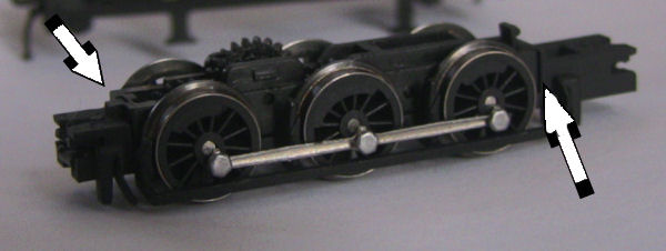
3. The brake gear is clipped to the wheel block at the front and back where indicated. Gently(!) bend the front and back of the combined unit and the brake gear will come away. If you did it gently you won't need to extricate the wheel block from the dog bowl. At least the wheels don't just drop out.
A quick update: The crank pinks are a push fit and can be removed by teasing them gently out of the hole. The coupling rods are very thin so take care not to damage them doing this.
The wheels simply un-clip from the frame with a small amount of upward force.
More after our appointment with the lathe at Saturday's area group meeting.
18 April 2009
Dapol Terrier
I picked up one of the lovely new Terriers which Dapol have just released and I am contemplating the best way to convert it to 9.42mm gauge.
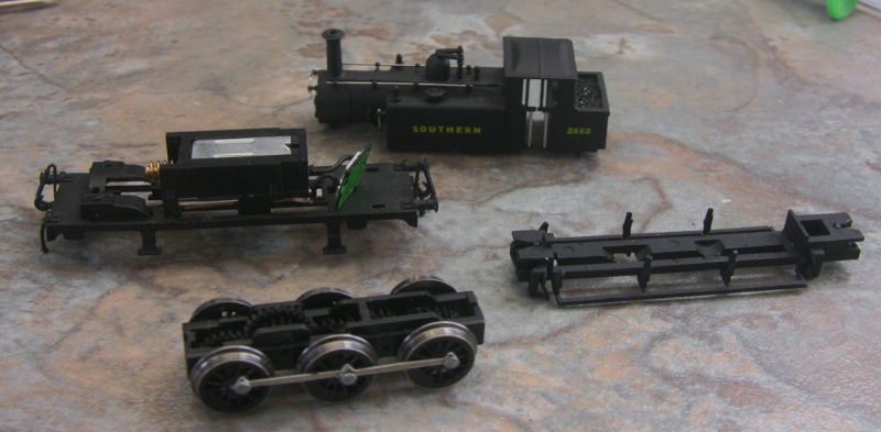
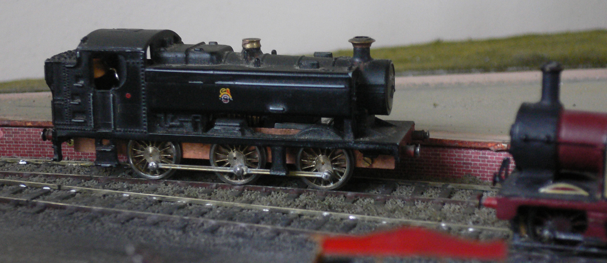
As you can see from the above I have already dismantled it. The resistor block will be discarded and a DCX74z chip put in its place.
Nigel has kindly offered to do some flange reduction at our next meeting though there doesn't appear to be much that could be removed. The wheels look pretty close to the 2mm standard (apart from the tyre width which is far too thick) and I am wondering whether pushing them out to 9.42mm gauge would be sufficient.
At present the wheels do not want to drop out of the frames - presumably the gears are keeping them in place? I wonder what the best method for adjusting the back to back would be?
The chunky plastic brake rods are going to foul the wheels when re-gauged and will probably be sliced off to be replaced with brass strip.
21 March 2009
The beginnings of "selham"
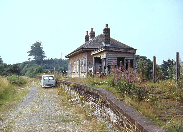
First I must point out that my first 2mm layout will not be an exact model of selham as originally planned, rather it will be a layout inspired by selham. My interest in the branchlines around Midhurst began as a child when passing Petworth station which is now a hotel I noticed pullman cars resting in the grounds. Later on reading "Branchlines around Midhurst" and its predecessor "Branchlines to Midhurst" that my interest in modelling the area was established. Originally I wanted to model Petworth Station as it was the station which I had passed so many times on my way down to chichester. Looking at the stations trackplan I quickly realised that at 2mm scale it would measure approximately 2.5m which I felt was a bit too much for my first stab at 2mm. Having looked at the other stations on the branchline, Selham instantly appealed to me through its remote setting, interesting trackplan, it simply oozed charm. Below is aphotograph of Selham station in 1968 following its closure in 1963.
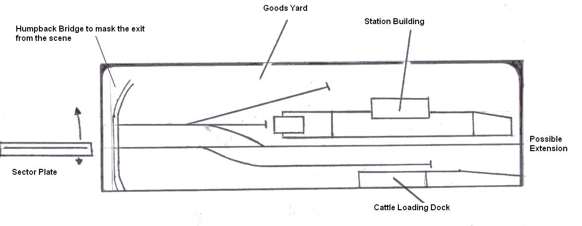
Like Petworth , Selham was of a similar size although on a sweeping curve. It was decided that the model I was to build would be inspired by Selham allowing me to compress elements of the station to fit into a smaller space aswell as being able to eliminate the sweeping curve which would simplify the build.
Below is the trackwork progress to date which shows the principal track to be pretty much finished. So now its on to the baseboard which I intent ot be styrofoam with plywood sides.
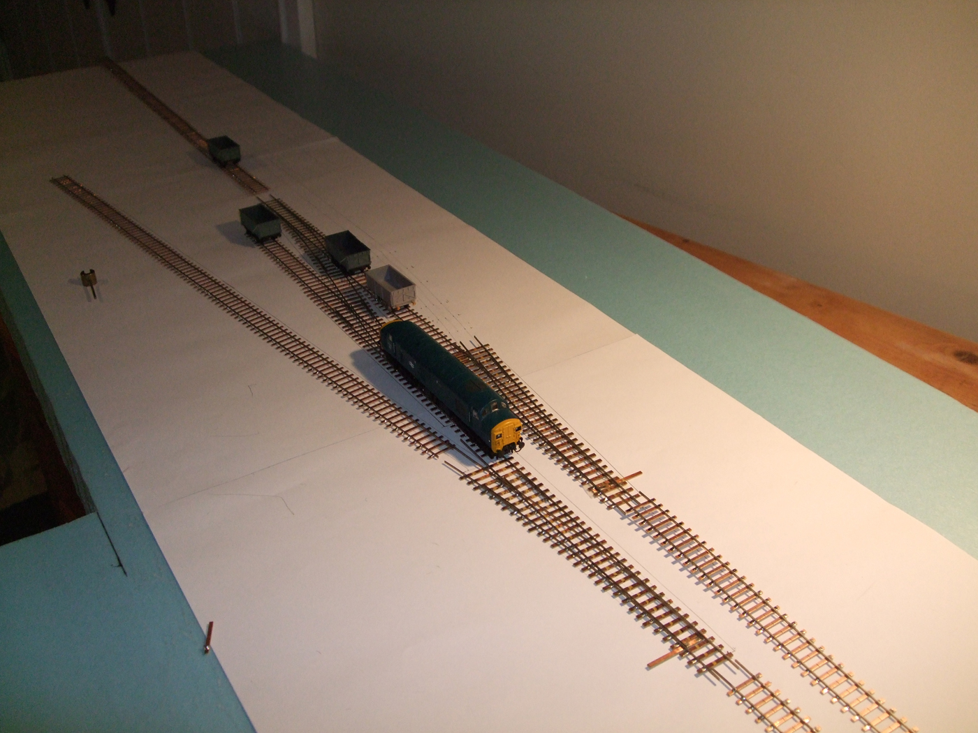
Motive power will initially be excellent farish class 37 and a class 04 with a 3F jinty to be built once I have got the layout up and running. Eventually I intend to converted a dapol M7 as something more indigenous to the area.
11 January 2009
Mounting DG couplings to NEM sockets
So that I have something to use whilst I devise and construct my first 2mm layout I have completed the installation of DG autocouplers on a small amount of my stock to use on my small n gauge layout. My German stock was converted in the normal way via the removal of the old coupling pocket and replacement with a DG coupler. All of the ride heights were set via a jig; simple blocks of plastic card to check the height of the mounting plate and after installation that of the buffing plate.
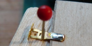
However the locomotive I had in mind for the shunting duties would need to have the DG couplers installed in an NEM pocket which necessitated the modification of the DG coupler to fit in the NEM socket. The coupling needed to mount in the NEM pocket and not move within the pocket once installed. The first step was to thin down the mounting plate at the couplings tail so that it would fit in the pocket. I then removed the lugs for the coupling loop.
A 0.85mm brass rod would provide the axle which would clip into the clips in the NEM socket and a short length of the same rod would be soldered along the tail of the coupling to prevent it from moving around in the socket. It was also provided with a 1mm offset to increase the height of the coupling in line with those heights found on my vehicles. I did this in the same way you would produce a joggle in point work. The finished coupling ( a bit blurred ) can be seen below.
The coupling was then chemically blackened and installed. Now to build my 2mm layout .....
24 December 2008
Farish 9400 conversion
In my last post I mentioned an experimental Association conversion kit for the Farish 9400 loco that had never made it to market. I had some left-over etches courtesy of Bill Blackburn and planned to use them to convert my own 9400 which was running like Long John Silver after too much grog as a result of my earlier botched efforts. Well yesterday I got it running and here it is:
It's a bit raw at the moment and a lot less forgiving of track imperfections than my Jinty, and its all-metal gears make a hell of a racket at full chat, but the Jinty got better over a few months of use and I'm hoping this one will too. Now it's back to landscaping the layout, once I've got the carbs back on the MG.
PS. If I paint a face on that capacitor, do you think it will fool anyone?
22 December 2008
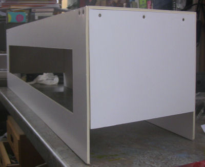
Baseboards from Foam Board
My inability to work successfully with wood led me to search for something more in keeping with my limited skills. Foam Board is a light weight board that is used extensively for promotional signs. It consists of a dense foam layer sandwiched between two layers of card . It is both light and strong and can be cut with a knife and a straight edge.
It also has some downsides: The lightness of the board means it is susceptible to damage and in its unpainted state it dislikes water (something I have already found out for myself).
The maximum length of foam board I could readily obtain was 1016mm so I decided to make this the length of each board. Using the computer I calculated that six boards 6 inches wide arranged as 6 sides of a decagon would just come in within the layout spec. However lack of storage for this many boards together with the prospect of completing them by 2010 resulted in the plan being scaled down to just three boards with the prospect of adding more at a later date if space permits.
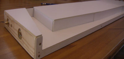
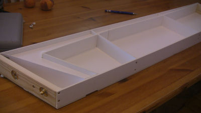
The boards are designed in two sections: The main board on which the layout is built and the fascia that covers it and will contain the lighting and backscene. The two are simply held together with bulldog clips - more than adequate for foam board. The removable fascia allows easy access to the layout when working on it.
The side and cross pieces are glued together but also screwed to keep them attached while the glue dries. To the top of this is added a solid foam board layer which is held solely by glue.
One difficulty I had was with the end pieces of each board which had to be angled at 18 degrees. In the end I copped out and used some 2 x 1 timber cut with a mitre saw to the required angle. The timber also allowed me to use pattern maker's dowels for alignment of the boards.
10 December 2008
My efforts to date
Here are some photos of the small layout that I started work on several years ago as a toe-in-the-water exercise. I've very little modelling exerience of any sort, apart from helping my father with his model railway in the 1960s and a bit of simple model-making when I worked in an architect's office in the 1970s. I retired last year, and finally blew the dust off the layout just before I came to our first meeting.
The whole layout is 120x30cm on a rather over-engineered timber, MDF and particle board base which I'm not sure I'd use again. However it does have the advantage that I can dribble solder all over the back of it and bash it with hammers without doing any damage.
The goods yard area (above) is almost finished. However, there's a lot still to be done on the whole right-hand end of the layout, especially the area around the station building (below), which is based loosely on Kingscote station on the Bluebell line. It doesn't look quite this ropey in reality, by the way; flash seems to magnify every little blemish!
Final picture above is of the Association wagon kit I've built, and my first loco - a scratch-built Jinty body on a Bob Jones chassis kit. Next project is to re-convert a Farish 94xx that I did myself right at the beginning, but this time using an Association coversion kit for the 94xx that never actually made it to market, kindly supplied as a one-off by Bill Blackburn. Then I guess I need to finish that station area, and think about scratch-building some LB&SCR carriages and maybe a Terrier loco. By that time I ought to have enough experience to plan a more ambitious layout.


