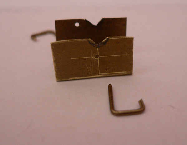
The coupling rods were straightened and re-attached. A little thought revealed that the two larger pins are for the centre wheels.
I thinned the brake rods down so that they cleared the wheels. The following photograph shows a comparison between the thinned side (at the bottom) and the original plastic at the top.

Assembling the chassis revealed that the brake shoes were touching the wheels in a few places. I repositioned them by briefly applying the tip of a soldering iron to the base and bending the shoes slightly forward. (I was not paying close enough attention when doing one and managed to melt the plastic where the brake rods are attached - this I still have to rectify).
The wheels have a tendency to turn on the axles if you give them a slight twist. Surprisingly, this seems not to be the problem it appears, probably because all the wheels are fully geared. However one wheel gripped even less and was found to turn while the chassis was running causing the wheels to lock up. I fixed this with some "engineering adhesive" (a loctite-type liquid I purchased from Eileen's Emporium some years ago). This refused to bite at first but after a couple of days it had gripped the wheel sufficiently.
The chassis then ran (up against a stop block) for a couple of hours without problem. I may take it to the next Wealden group meeting to give it a chance to stretch its legs on Nigel's portable test track.
I re-soldered the chip with shorter wires (including re-soldering one wire where it attaches to the chip to allow it to bend at right angles) and the chip is now less obtrusive in the cab - if you squint it could well be a fireman hunched over his shovel though this is not going to pass any close up photography tests!

The only matters left outstanding are the repainting of the wheel rims and the fact that the body is refusing to sit snugly against the chassis for some reason, but that is something for another time.
This has been a very quick and easy conversion, thanks in part to the extensive help I received from fellow members of the Wealden Area Group.