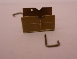
I'm always looking for rough-and-ready ways of getting things done, often so rough that I end up having to do it all again, but this one worked well. It's only any good for locos with identical spoked wheels on all axles.
All that's needed is a bit of brass sheet thin enough to slide between the outside face of the chassis and the back of the wheels when the back-to-back is set correctly. Bend the sheet into a rough U shape as in the photo, file a couple of notches in the 'wings', then assemble the wheels on a muff in the chassis and wriggle the wings up behind the wheels so that the notches fit under the axles. Turn the left-side wheel until the crankpin is facing downwards and drill a hole through the wing in the gap beween the spokes adjacent to the crankpin. Push a bit of brass wire through the hole so that the wheel can't rotate. Obviously the wire needs to be a tight fit between the spokes and in the hole. Now rotate the other wheel until its crankpin is at 90 degrees (ish) to the first one, and drill a hole between two spokes on that side. Pop a pin in and make sure both wheels are locked in position.
Remove the pins and the tool, and you now have a template for positioning the wheels on the other axles. I found that the coupling rods dropped onto the crankpins first time, and only a hairsbreadth of adjustment was needed to relieve a minute tight spot.
The tool is a throw-away but it only takes fifteen minutes to make, involves no measuring or marking-out and costs nothing.


