Am I alone in making more progress in the immediate aftermath of an area group meeting than in the whole of the rest of the month? Following yesterday's dose of Wealden inspiration I finally got round to tweaking the single Turnout Operating Unit (TOU) on my "scenic test track" and spent a pleasant half hour running trains back and forward through the turnout. Simple pleasures, eh?
This TOU has been an ongoing saga (though other Wealden group members will probably tell you that applies to anything I touch). It was built initially for servo operation but converted to manual operation when the servo board I was using gave huge over swings at start-up. After building a fascia I didn't really want a piece of brass operating rod protruding through it, and having enjoyed the delights of running trains using Engine Driver on an Android phone, I wanted to control the turnout and magnets using DCC too.
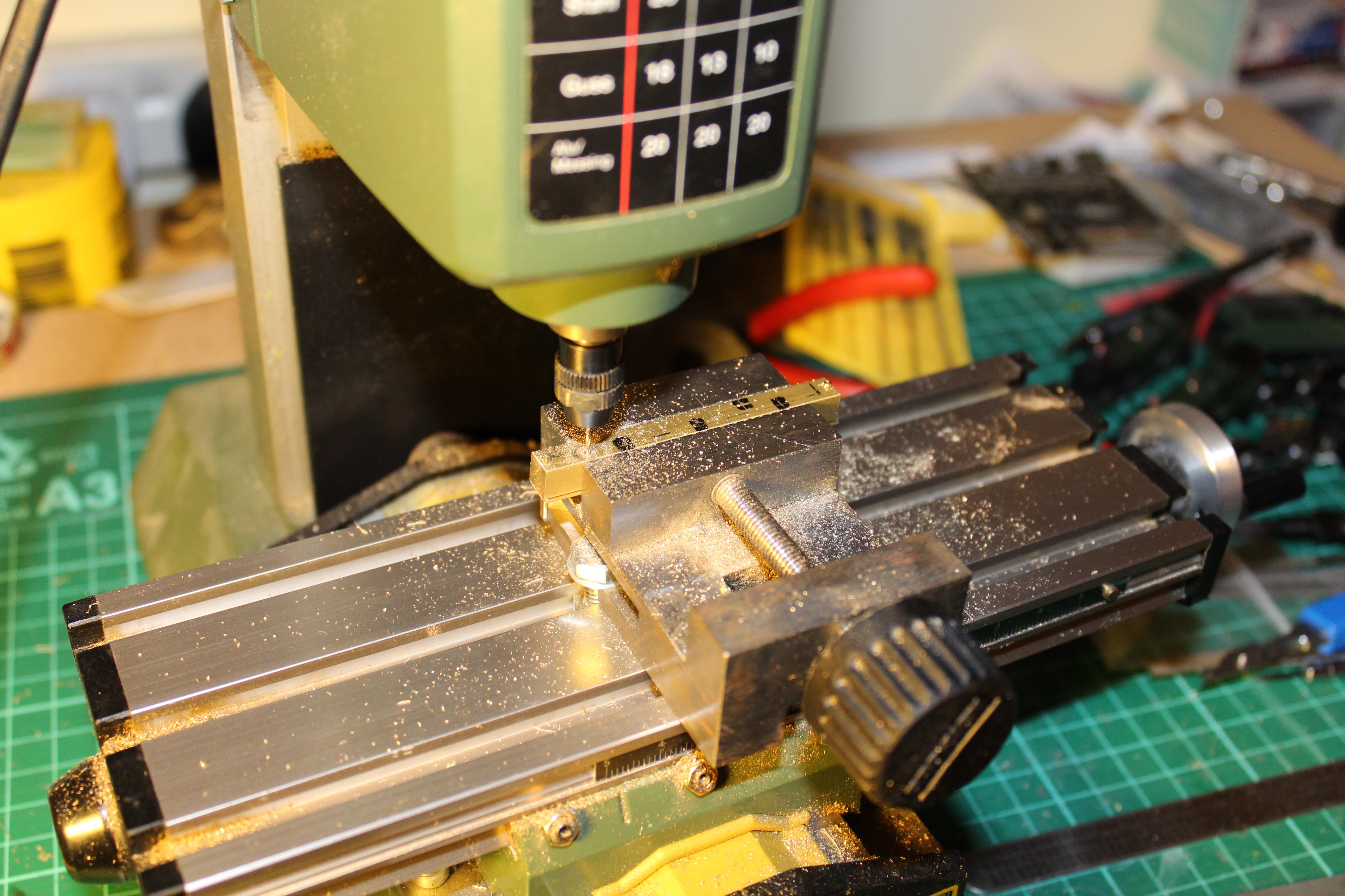
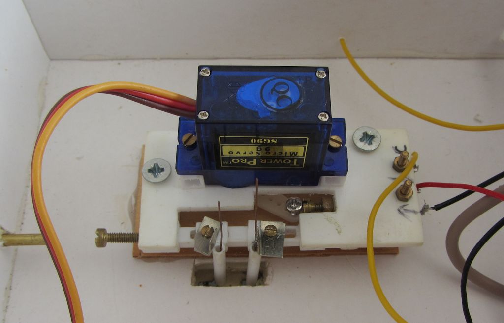
The TOU (below) is based on Geoff Jones' idea of telescopic styrene section. The droppers from the switch blades come down the tubes in the middle which have screws that slide in the slots just visible to provide plenty of scope for adjustment. The dropper on the right is soldered to the metal L section as this switch blade has a tendency to lift. The screw on the left is left over from when the TOU was worked manually - the operating rod came through the brass tube just visible on the extreme left.

There is a microswitch on the right hidden under the screws). This is worked from a screw just visible to the front right of the servo which is fixed to the slide bar and which can be adjusted so that the microswitch throws reliably. The microswitch also provides the return spring for the slide bar so that it is only necessary to precisely adjust the servo for one direction of travel. You can see the servo arm peeking out from underneath where an attached screw presses against the microswith screw and moves the slide bar. Much simpler to do than describe!
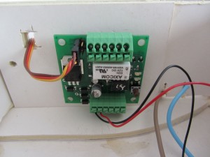
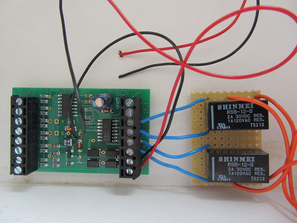
The Team Digital Servette (above) drives the servo. This was purchased as it has a Relay with a separate DCC address that I planned to use to work the electro-magnets but when doing this I experienced occasional twitches of the servo when the magnets were operated that threw the switch blades to a different position - not what you want when propelling wagons over a turnout! These twitches were intermittent, perhaps 1 in every 10 - 20 throws, so debugging was a convoluted process. To start with I swapped to a spare NCE Switch-It that I had lying around (below) which switches relays that control the magnets.

This on its own didn't help and after wrongly suspecting the proximity of the devices I eventually discovered that it was due to the leads from the magnets passing close to the servo. After moving the Switch-It to the other end of the board so that the magnet wires completely avoided the servo, the problem disappeared. What I should have done was experiment to discover just how far away the wires needed to be, but by this point I was just pleased to get it working!
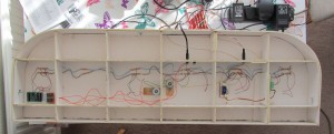
The picture below of the under side of the board shows the Switch-It at left, the magnets centre and the TOU and Servette to the right (plus a lot of messy wiring).
Adjusting the swing of the servo was a doddle using JMRI and the adjustable dropper tubes made it easy to get the throw of each blade exactly right. I have set up a small panel in Panel Pro which makes it easy to control the turnout and magnets.
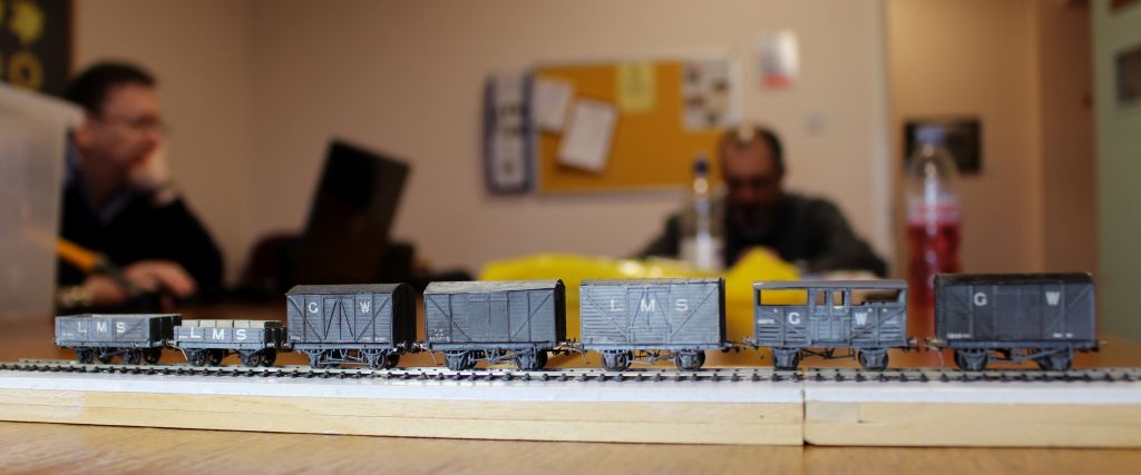
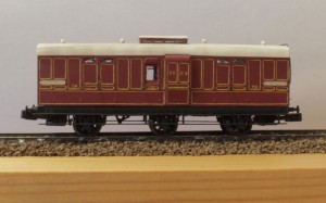
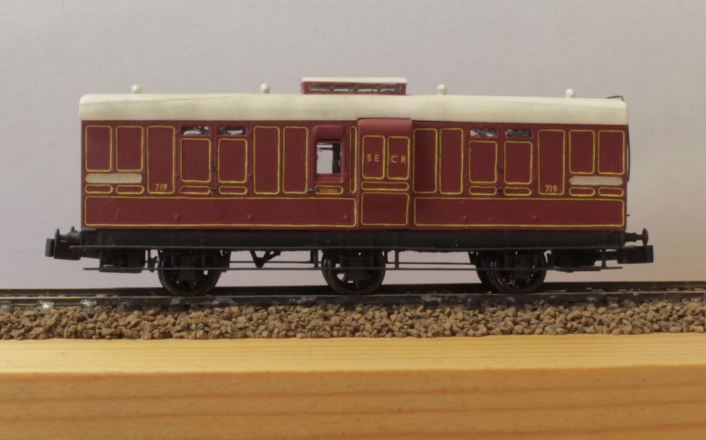
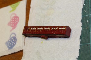
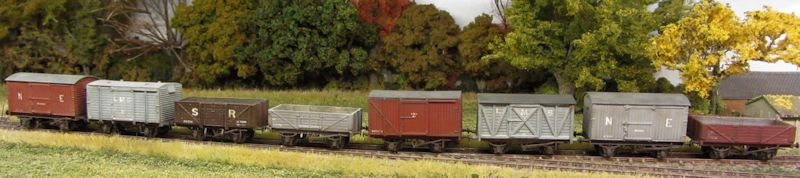
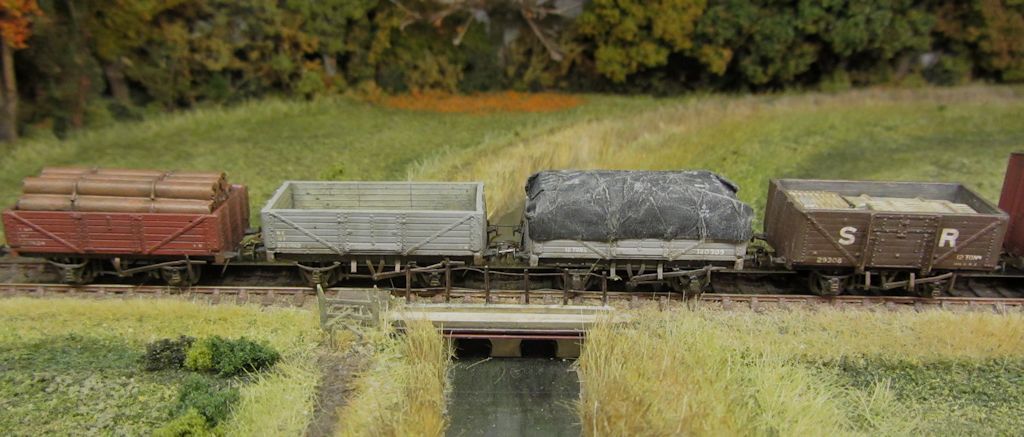
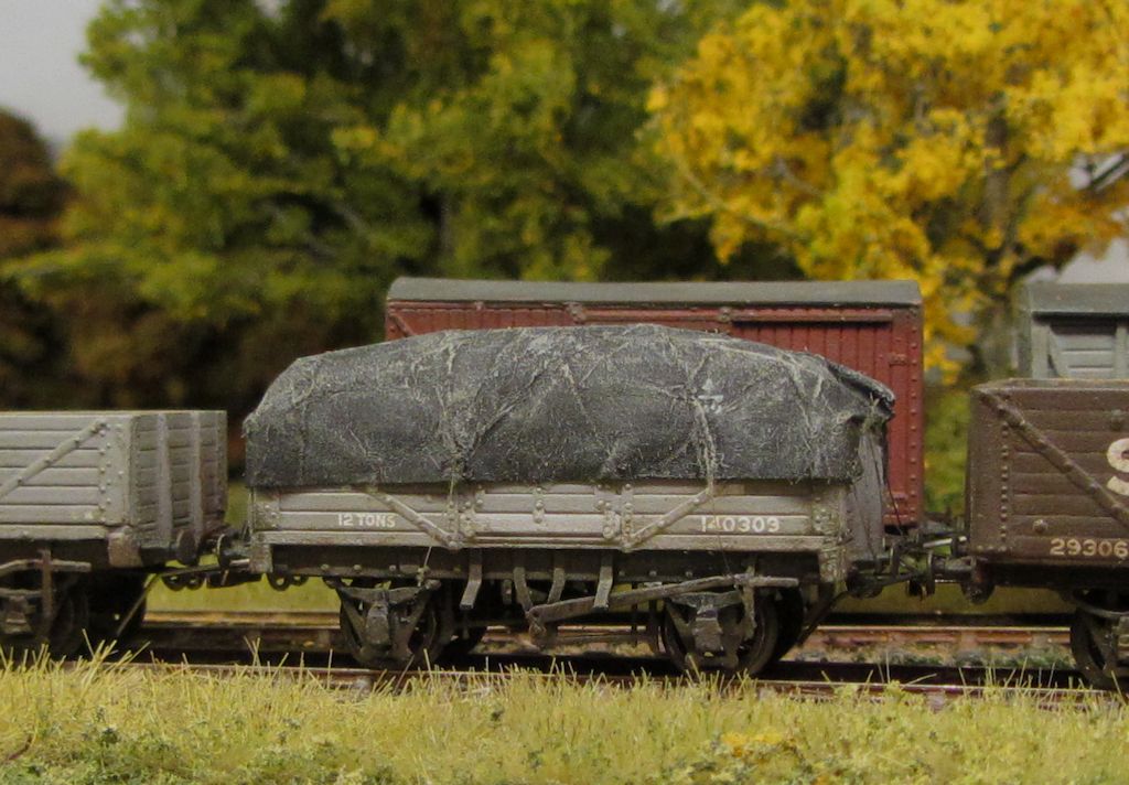
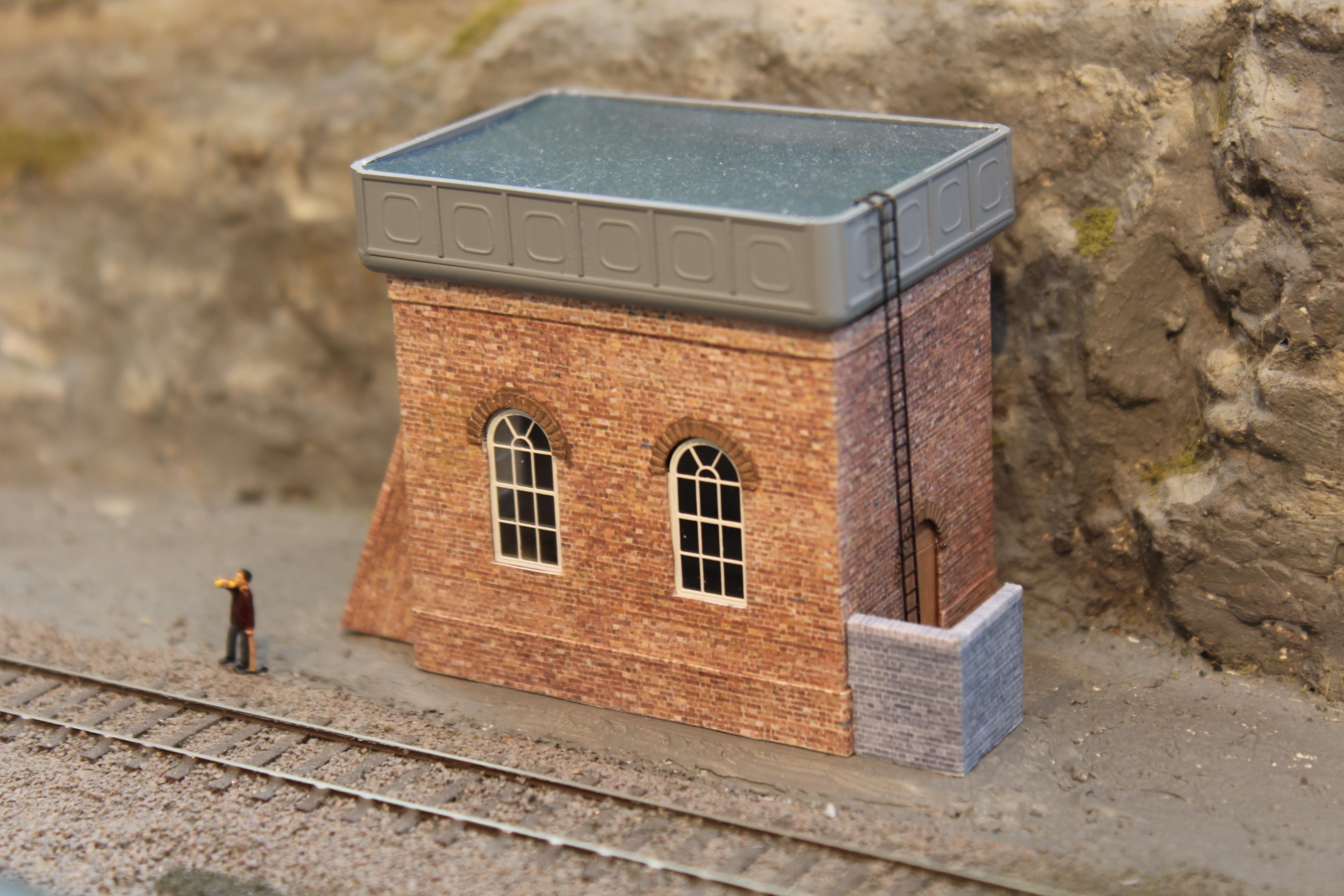
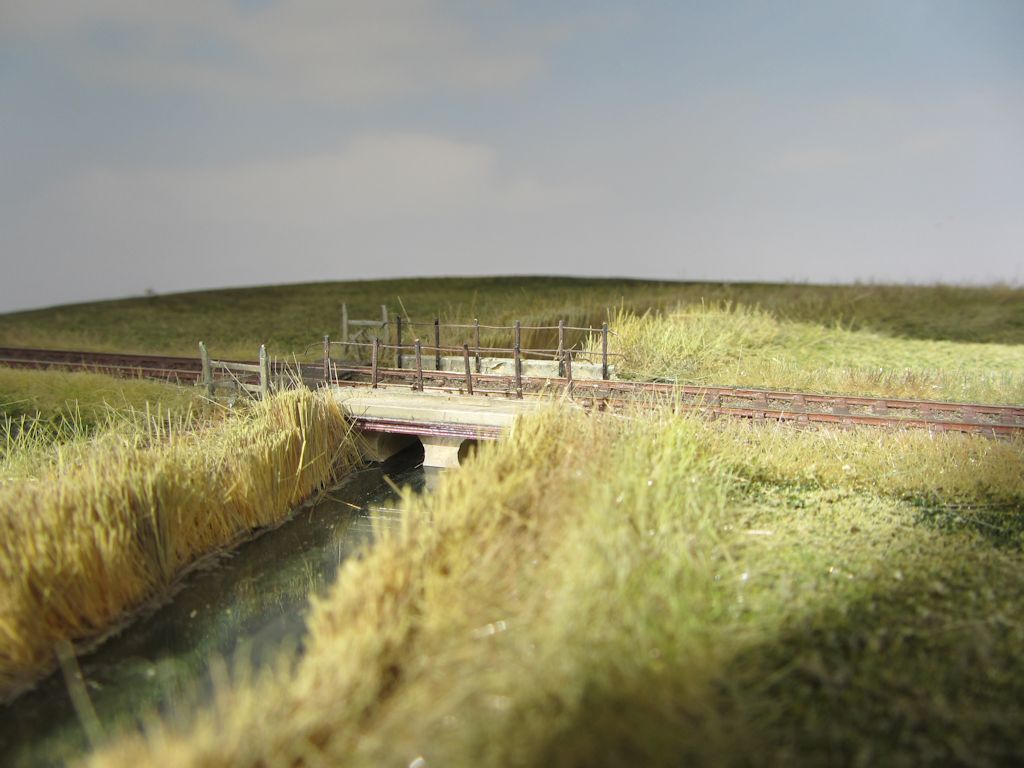
And with that done I can get back to the fun stuff:

The reeds need tidying after being upside down for the above adjustments but I am quite pleased with the colouring. I am in the middle of creating trees for the background using dried stalks based on the Fencehouses article in MRJ though I really need to do the line side fencing first.
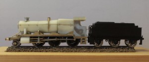
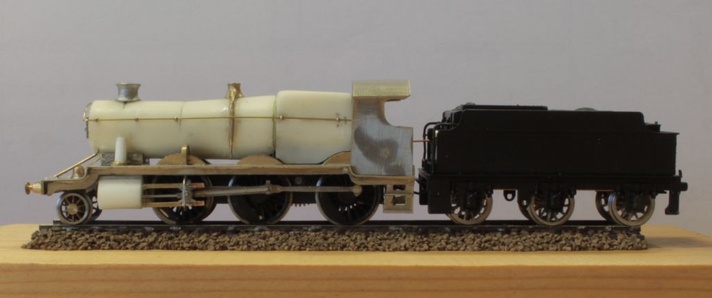
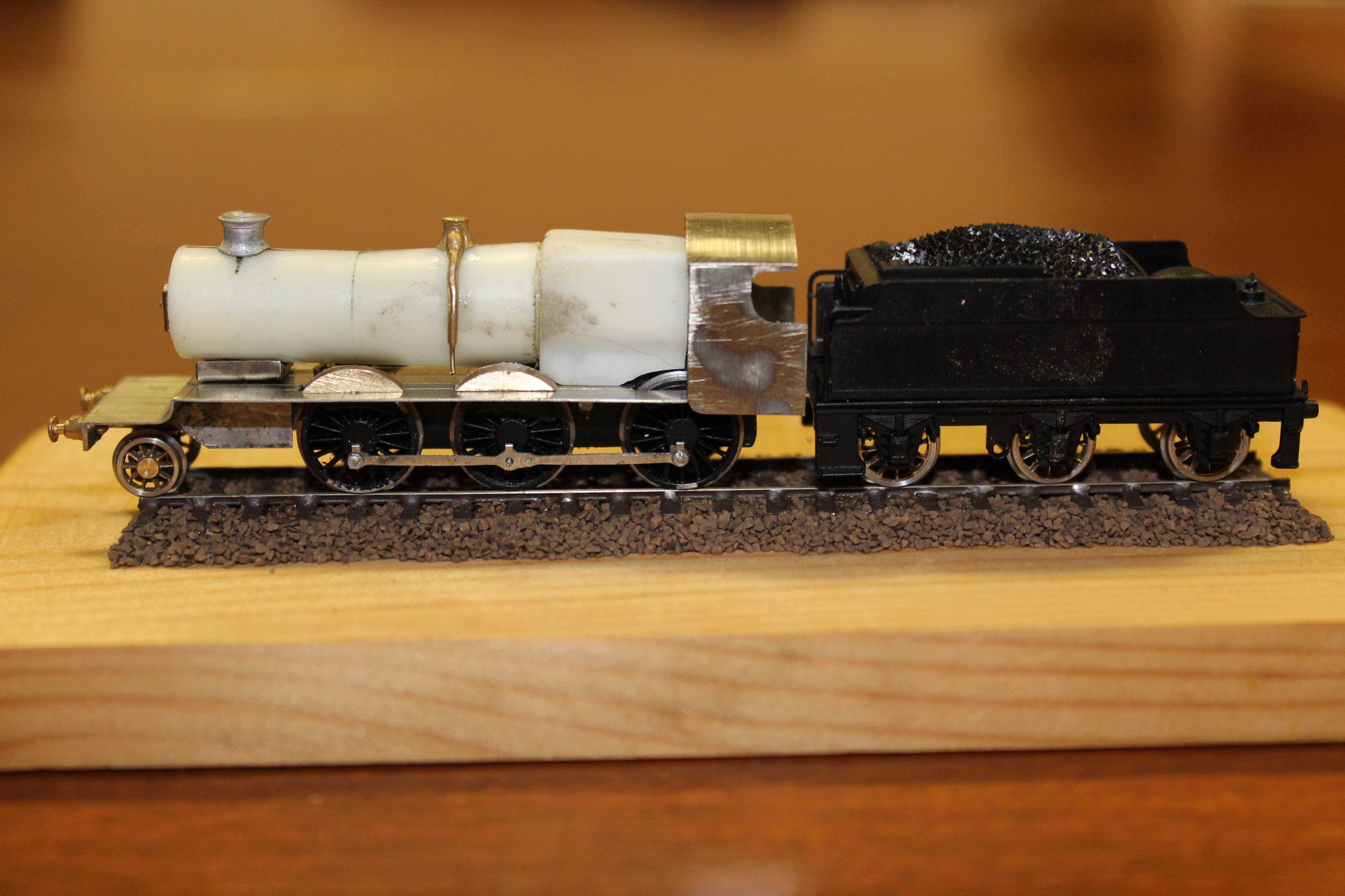
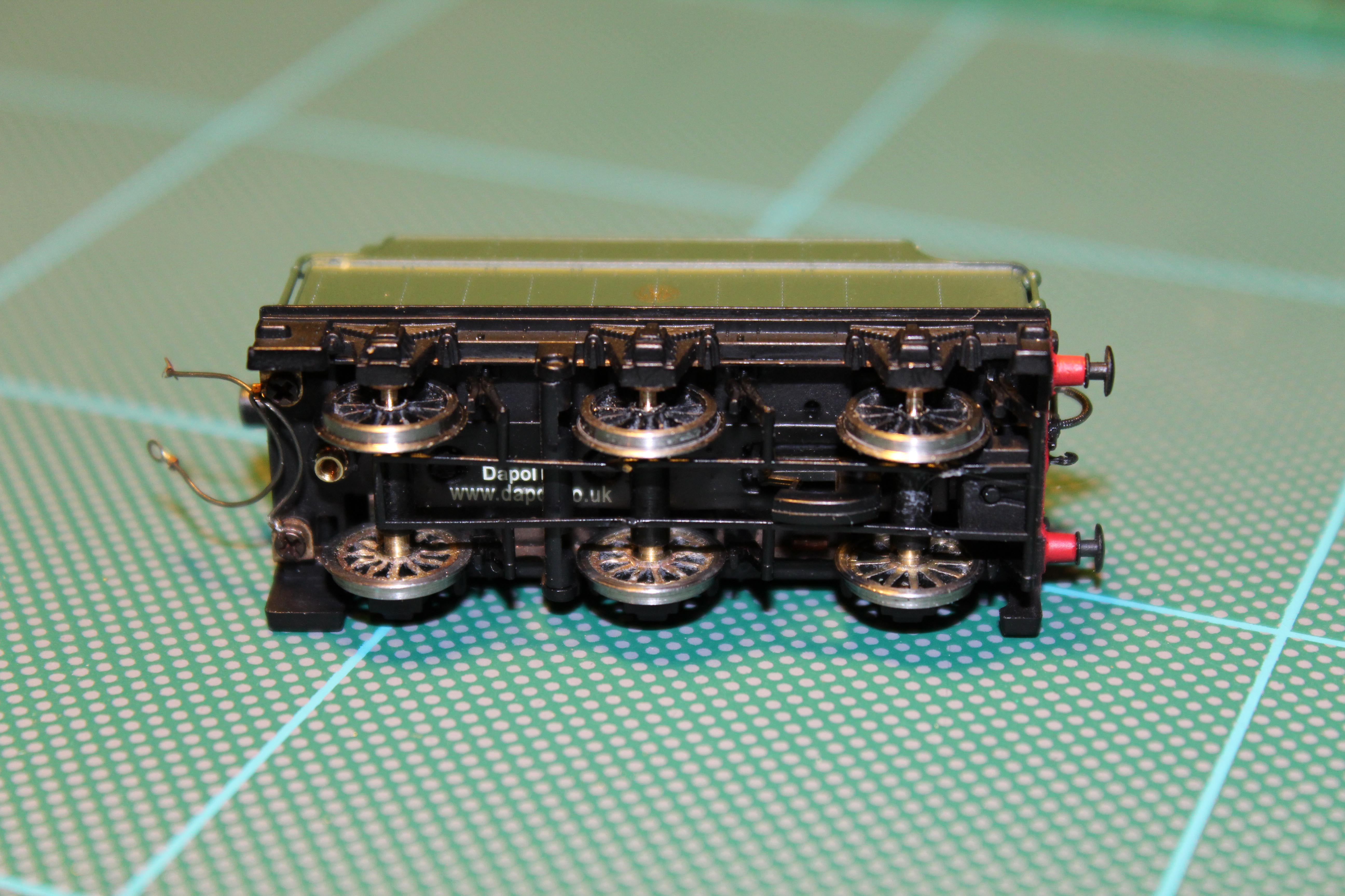
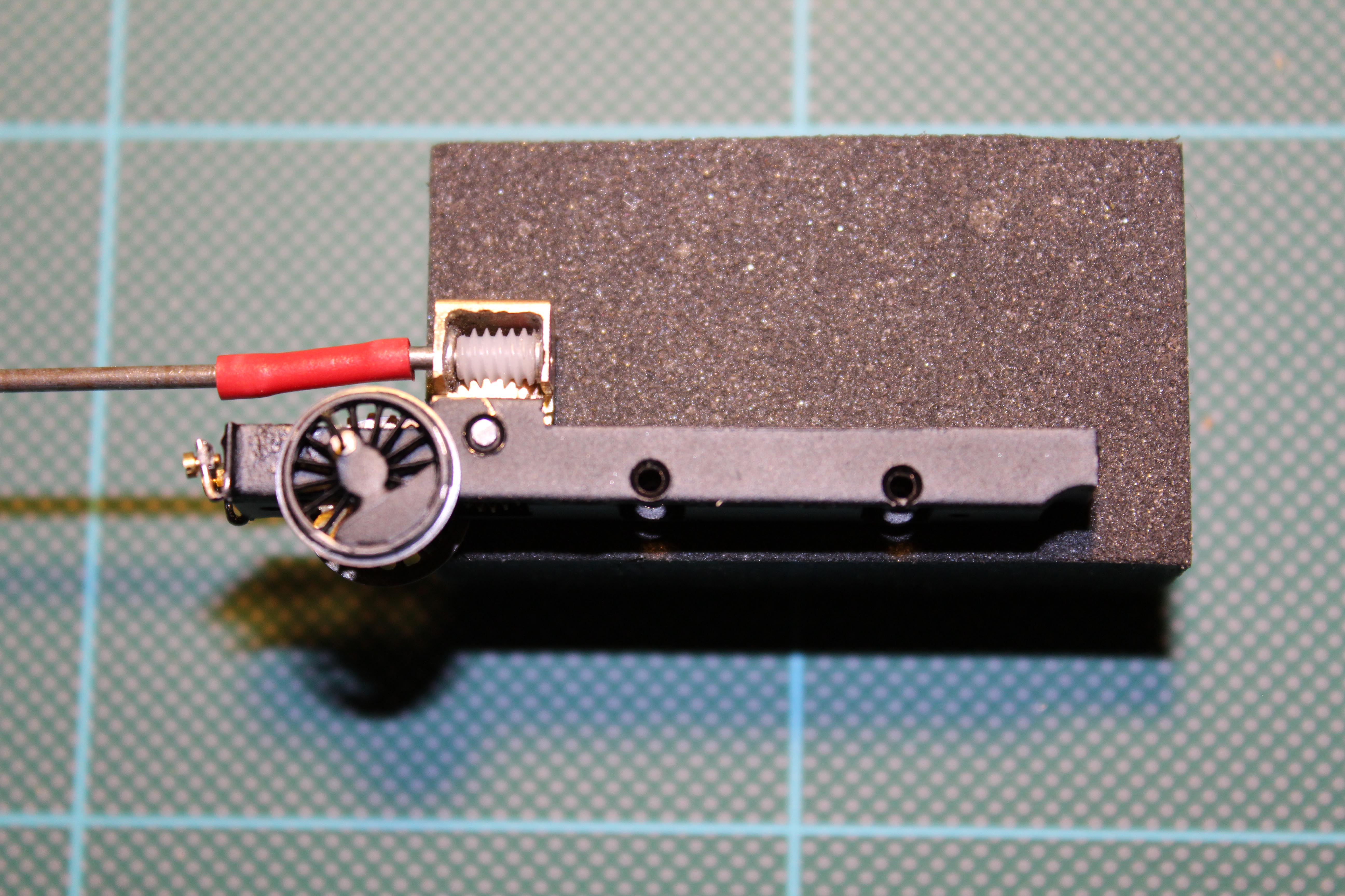
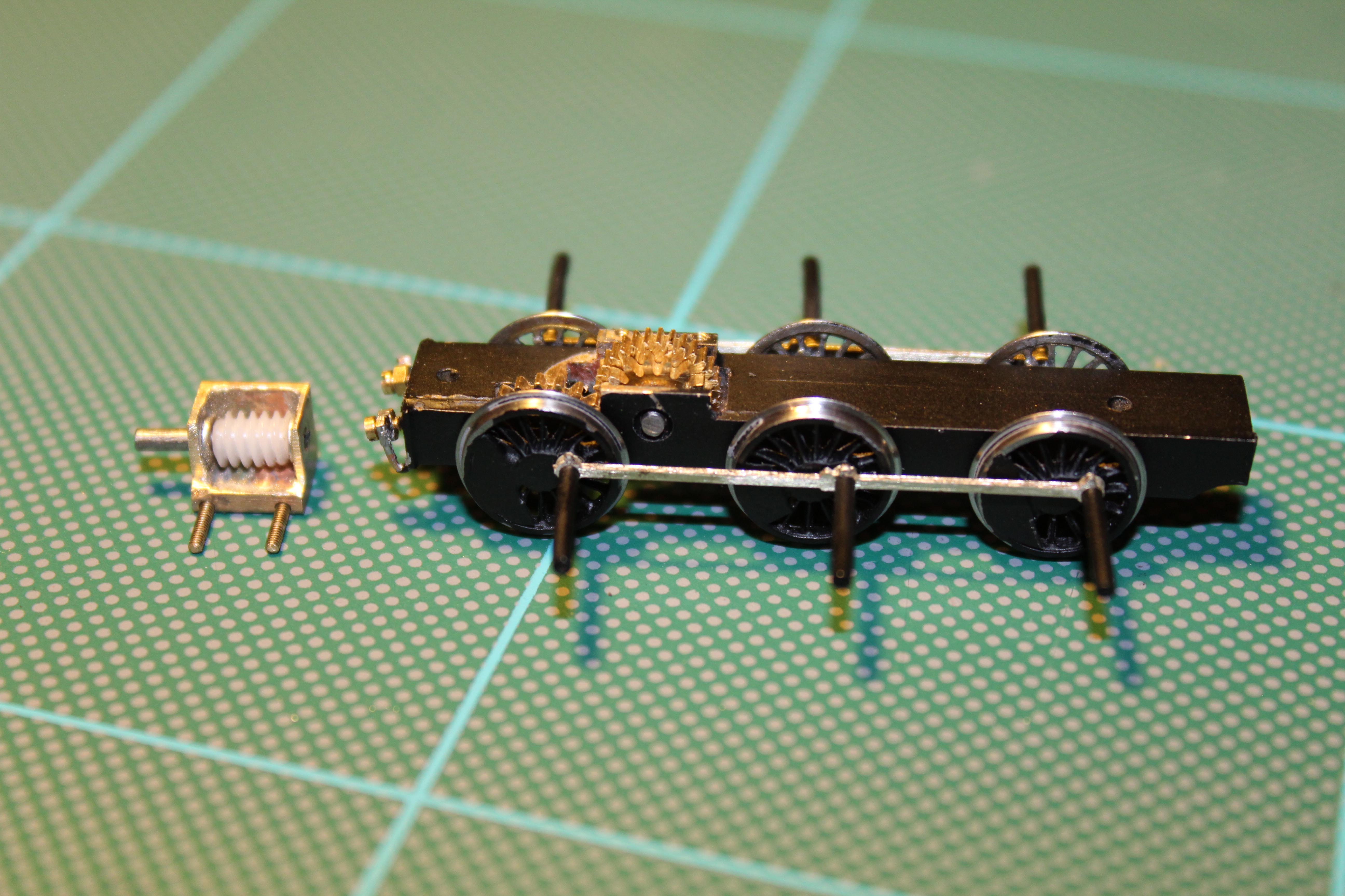
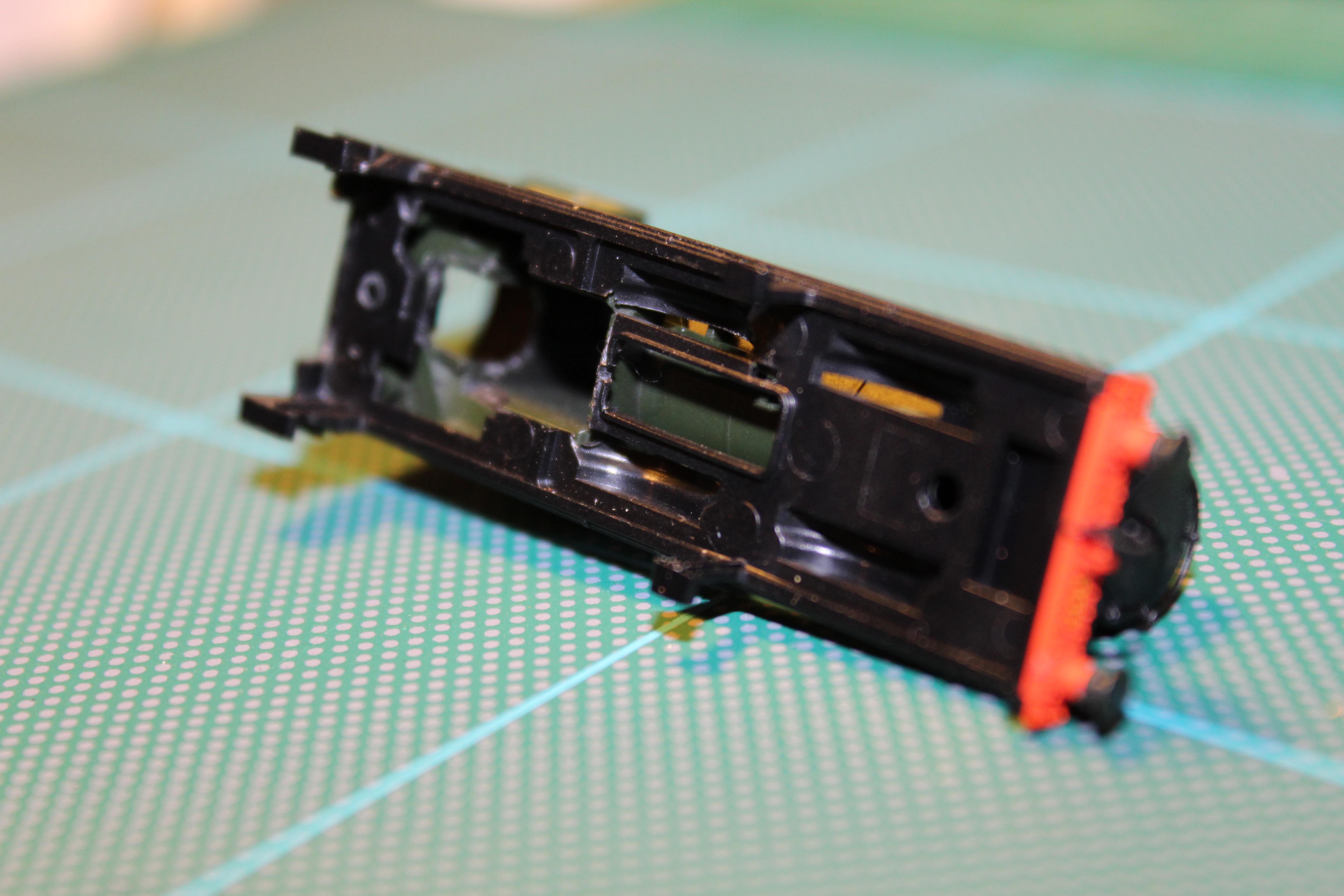
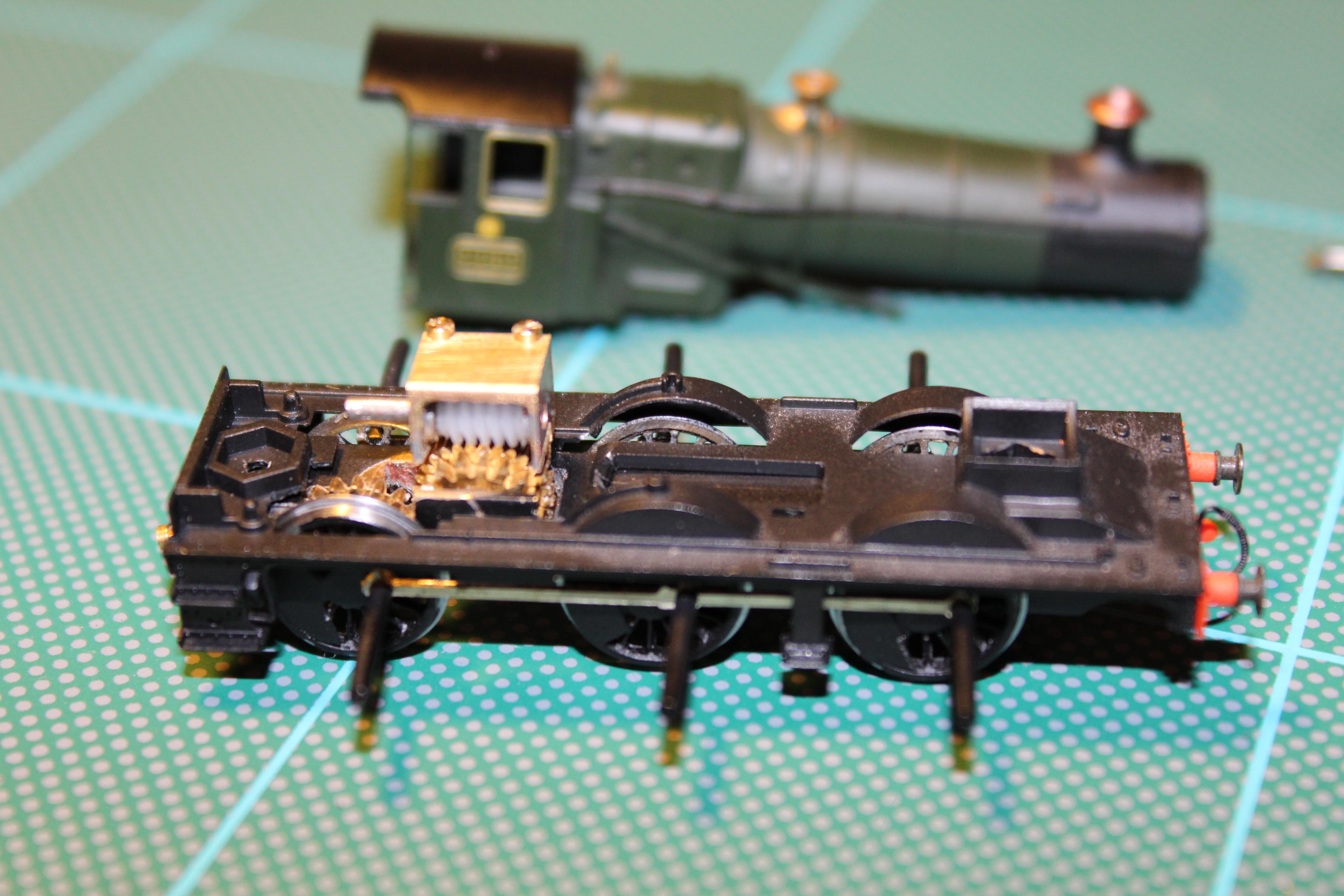
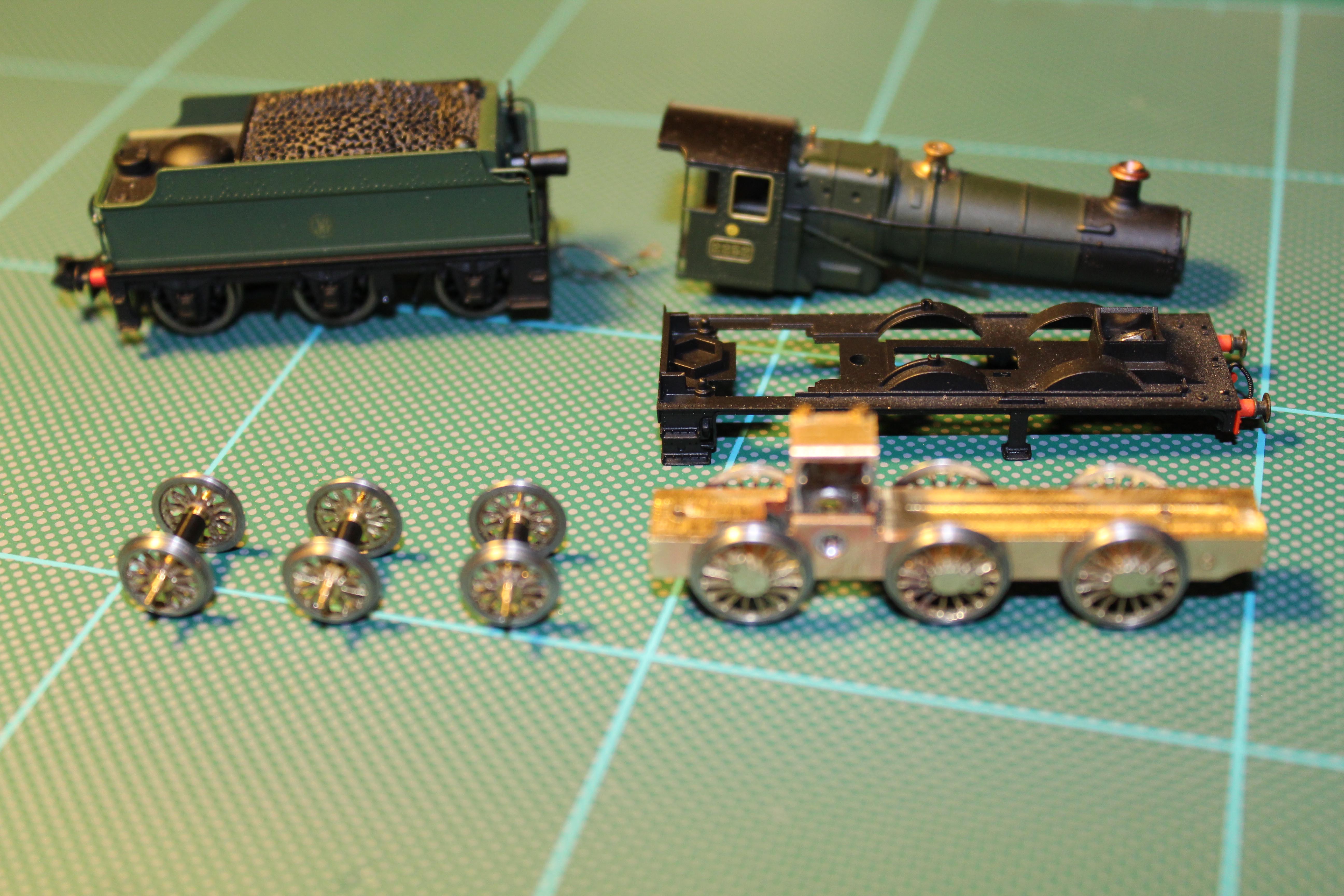
But for now back to the N2 underframe...