No, not describing the time it has taken since our last post (although that would also apply), but the fact that we managed to meet up in person in a larger room and correctly distanced.
As the last meeting was at the beginning of March, this meant 6 months since our previous get-together and clearly some modelling has been done in the intervening period.

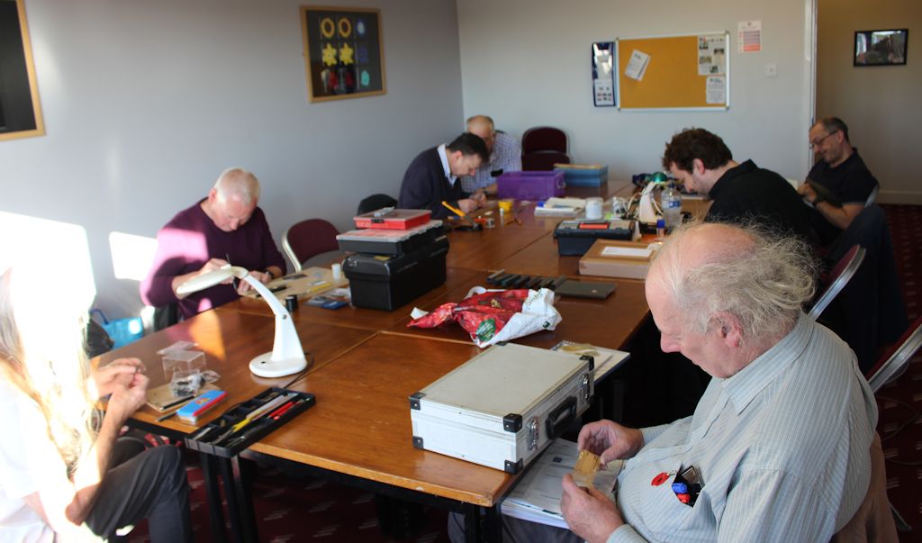
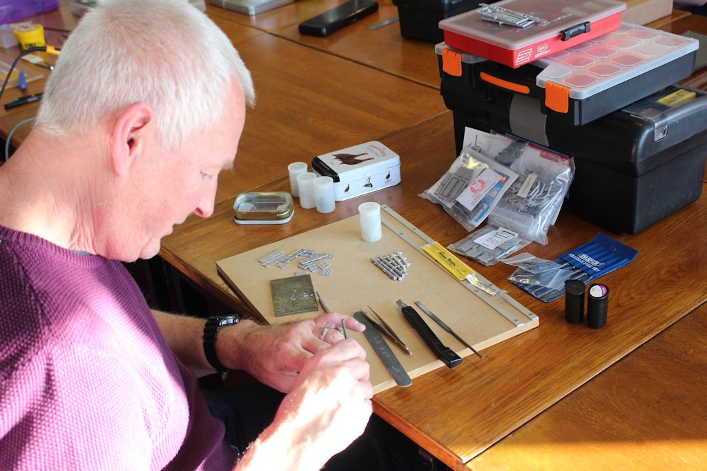
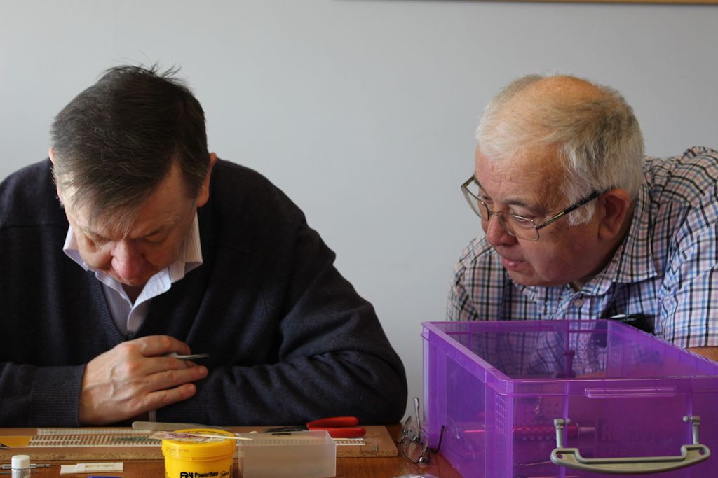
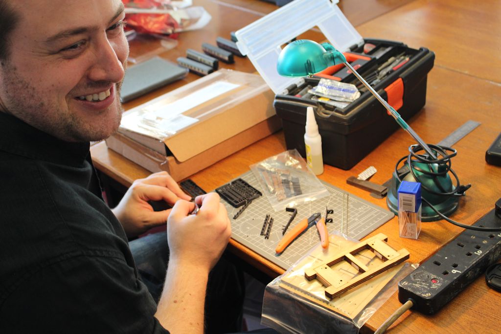
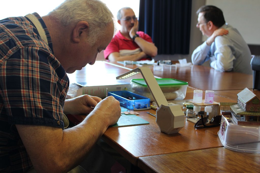
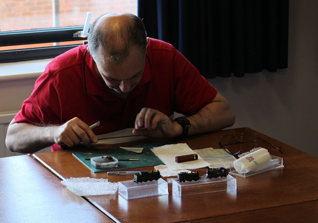
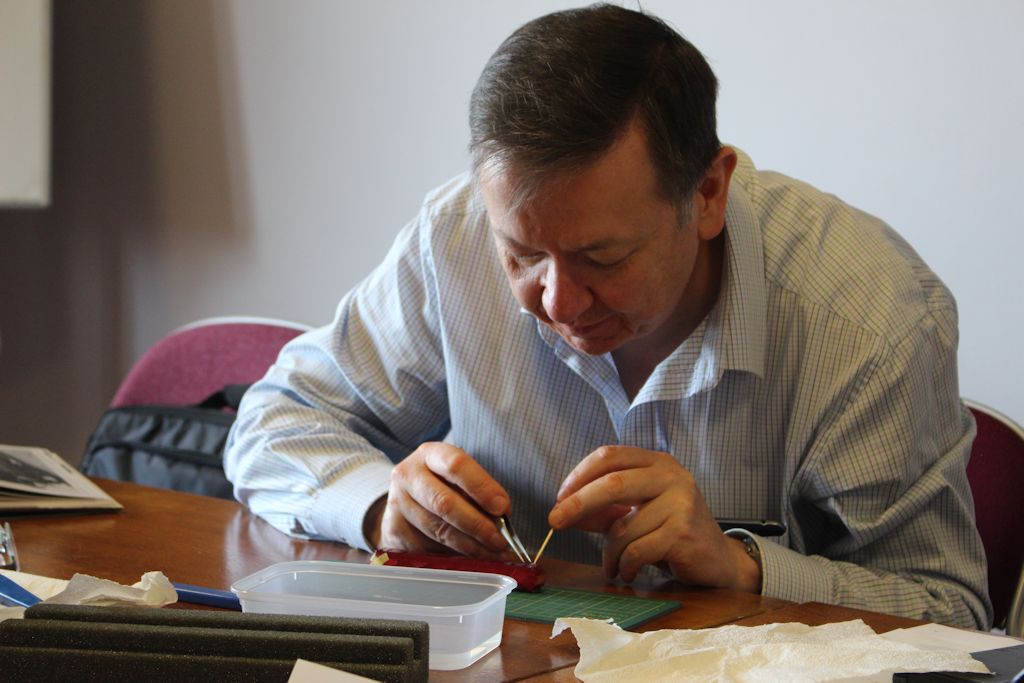
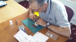
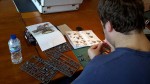
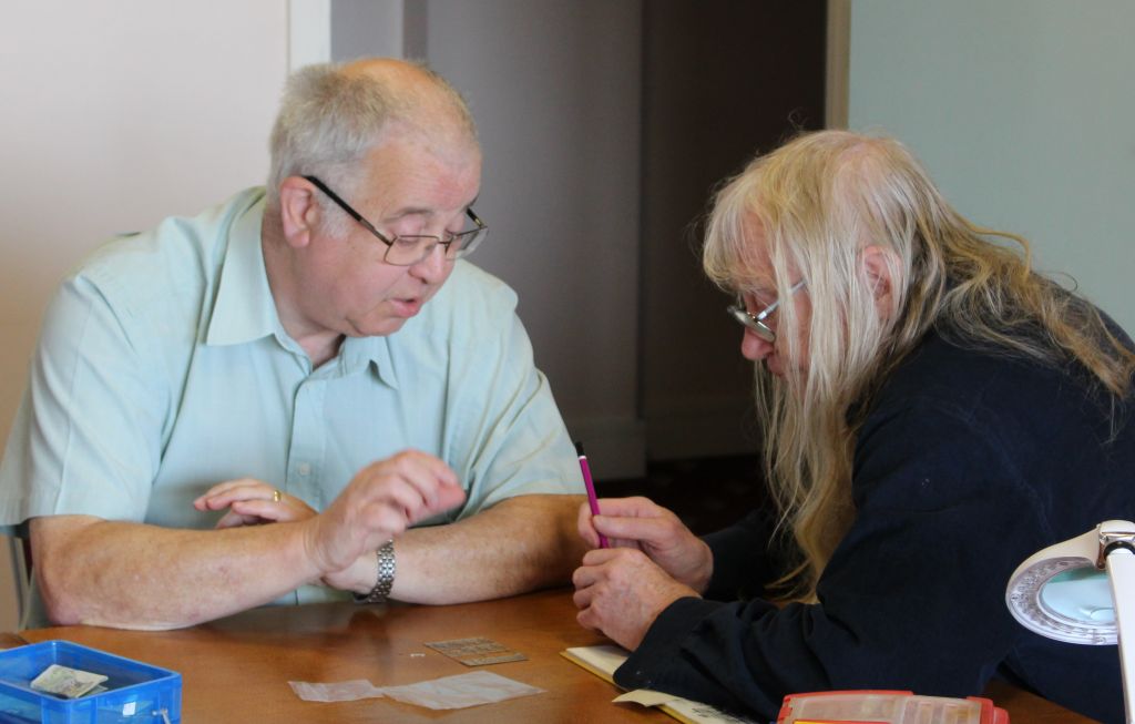
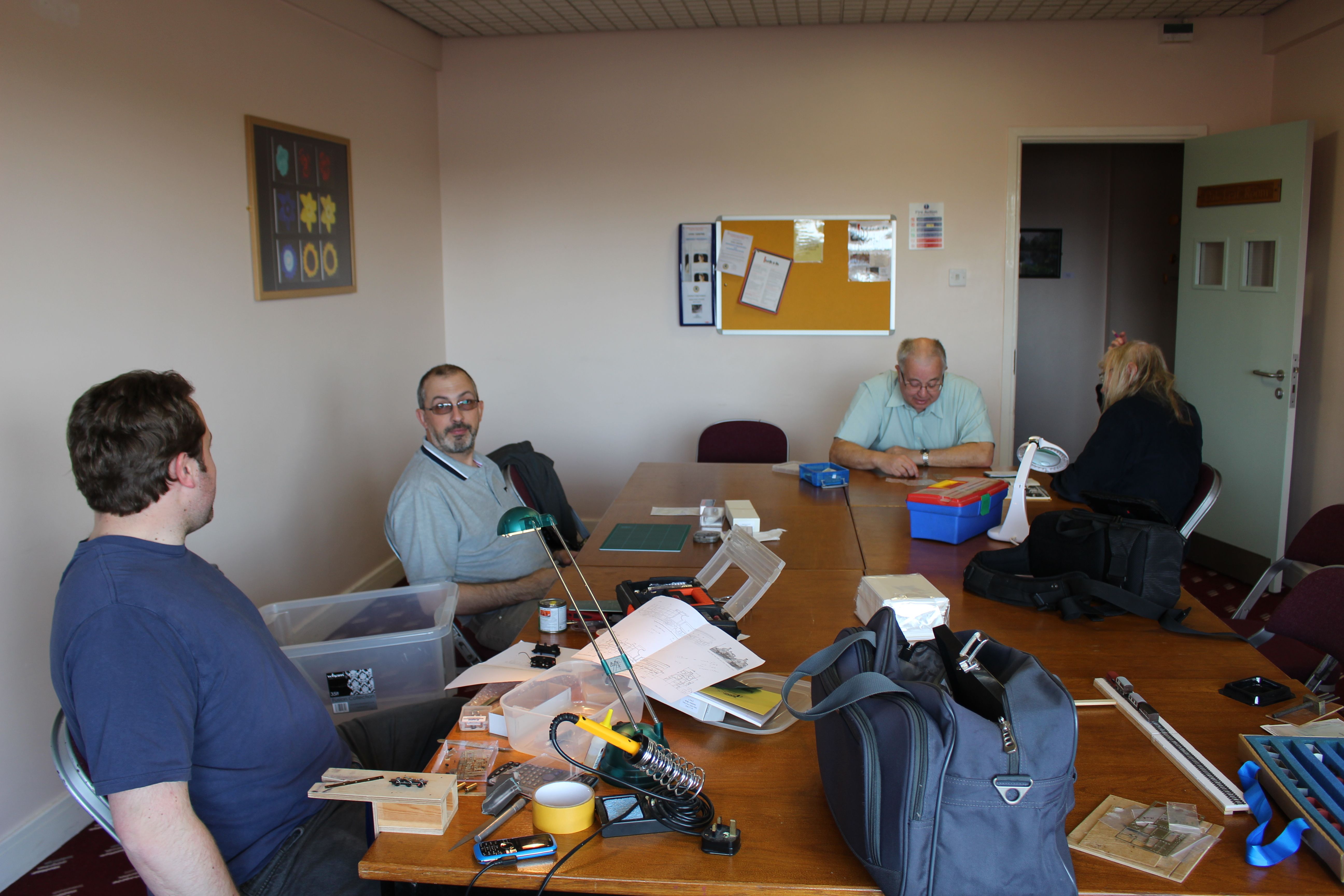
Gareth, Dave, Simon, Alan and Nigel started and Peter joined soon after this picture was taken. The extra space allowed a degree of latitude with face coverings at the allotted work stations, but we masked up when moving around or getting a tad closer to peer at various models.
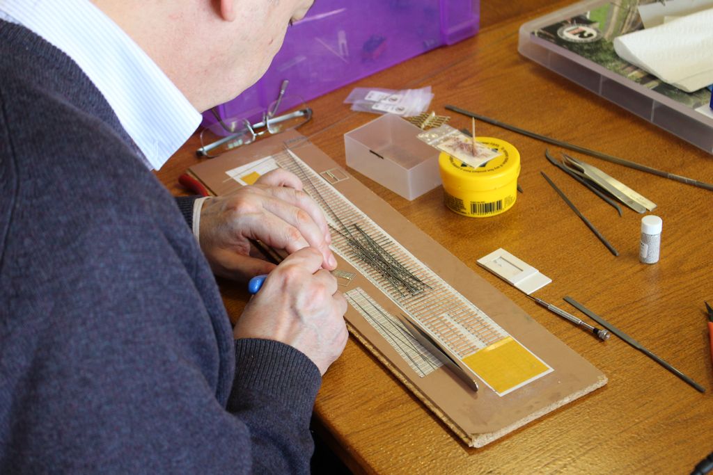
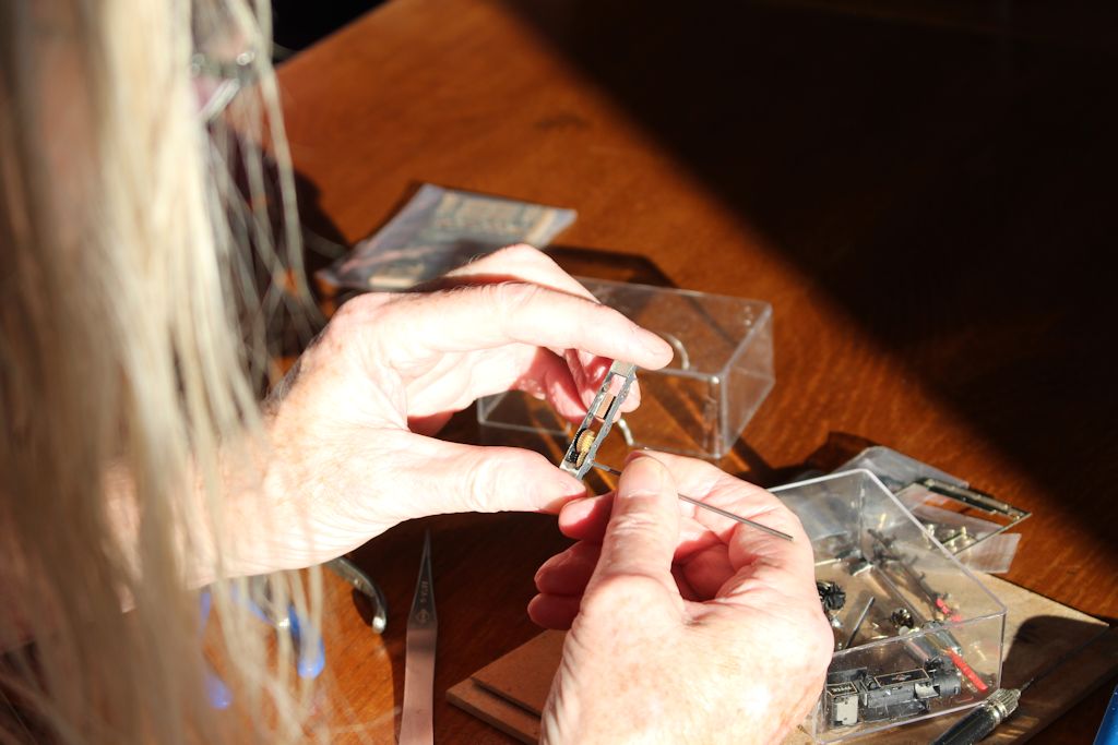
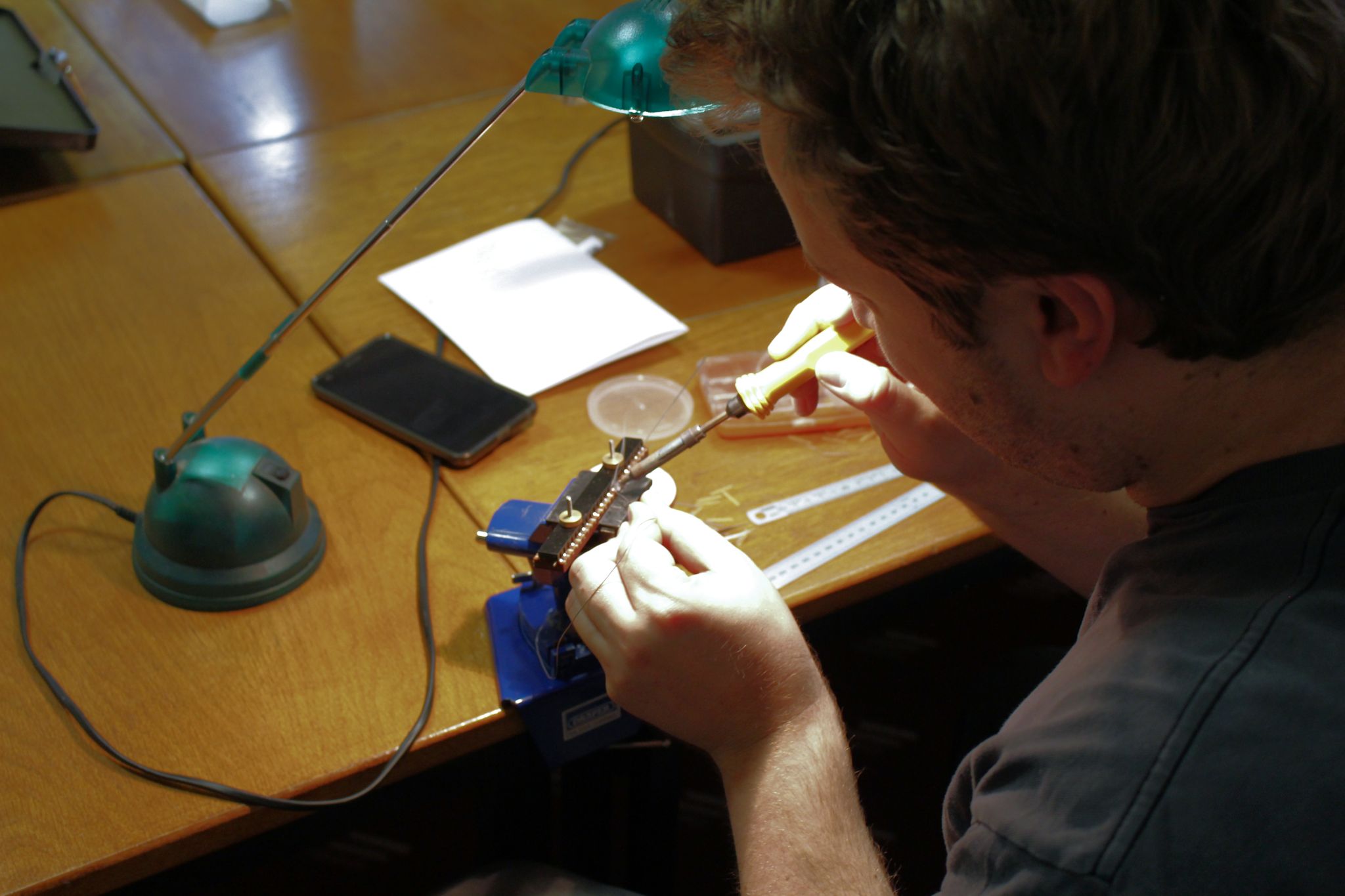
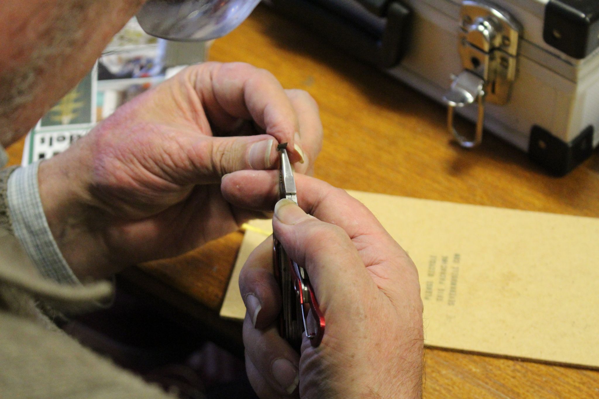
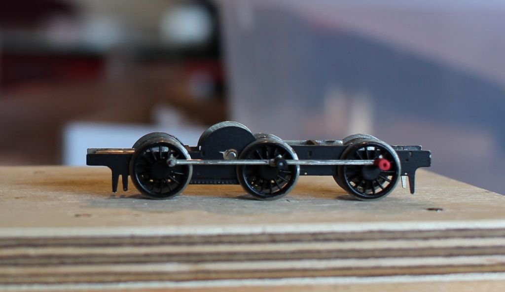
Dave described a flexible chassis he was working on with fine piano wire as springing while Peter has been making further progress with Radio control.
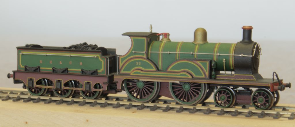
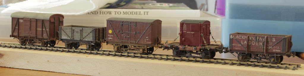
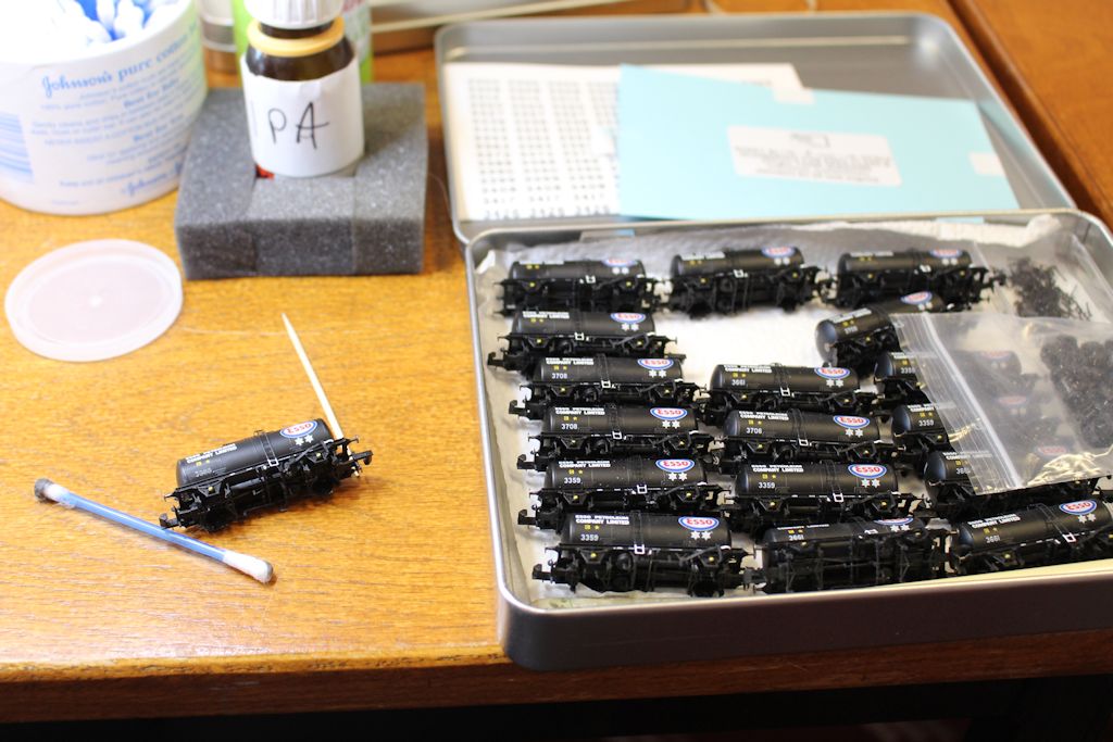
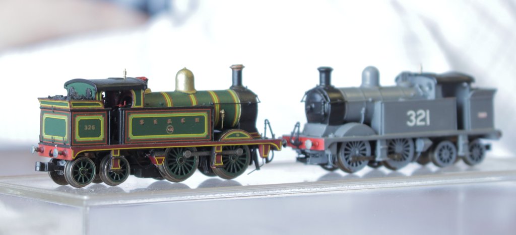
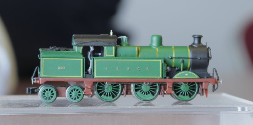
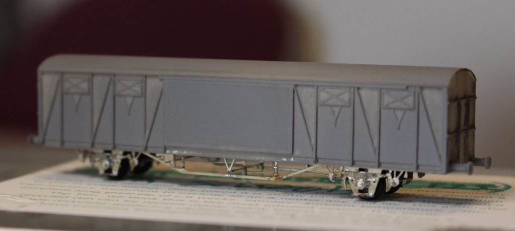
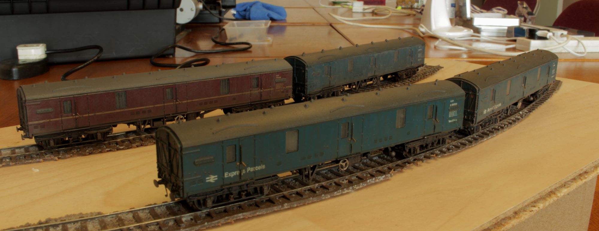
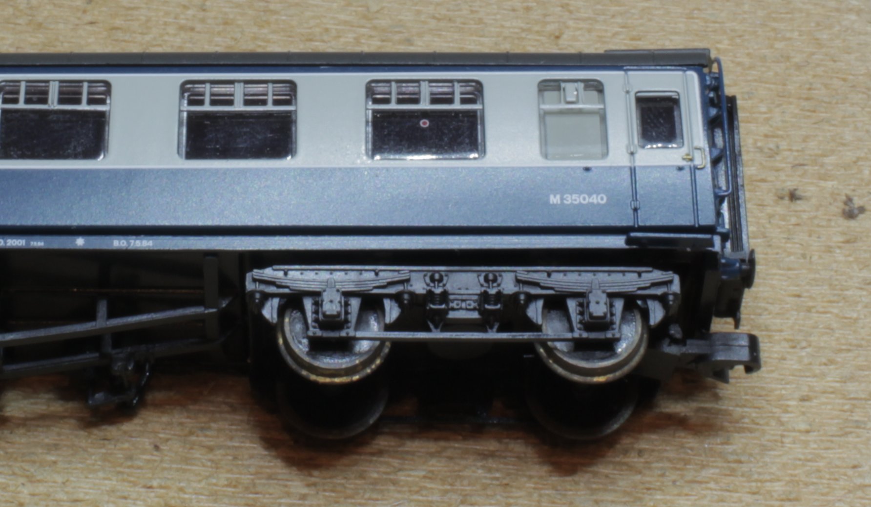
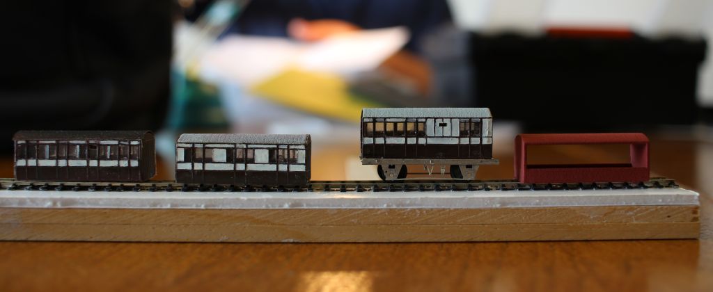
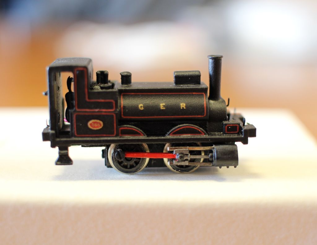
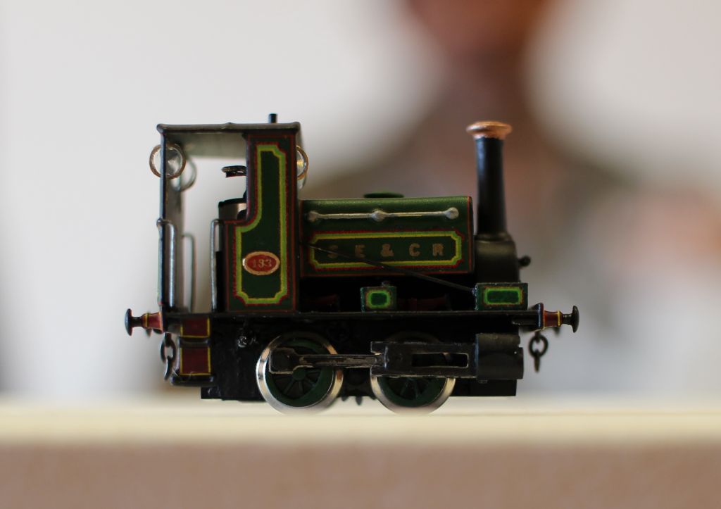
Simon has been busy with more wagons while Gareth has been his usual creative self with a couple of SECR's finest.
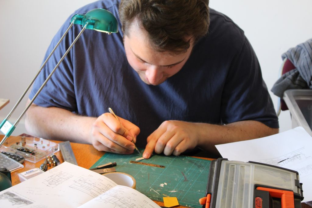
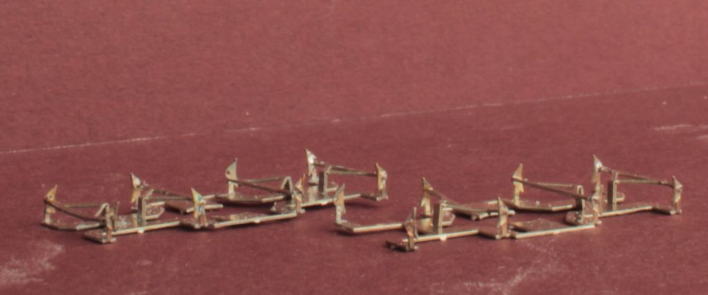
Alan has been building the Association 08 shunter kit and was discussing refinements with Nigel. Everything lined up but needed a tad more play in the axles to get a free running chassis, so more a bit of fine tuning.
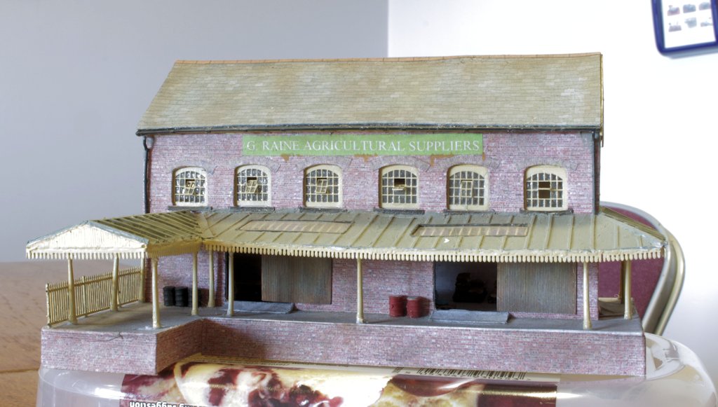
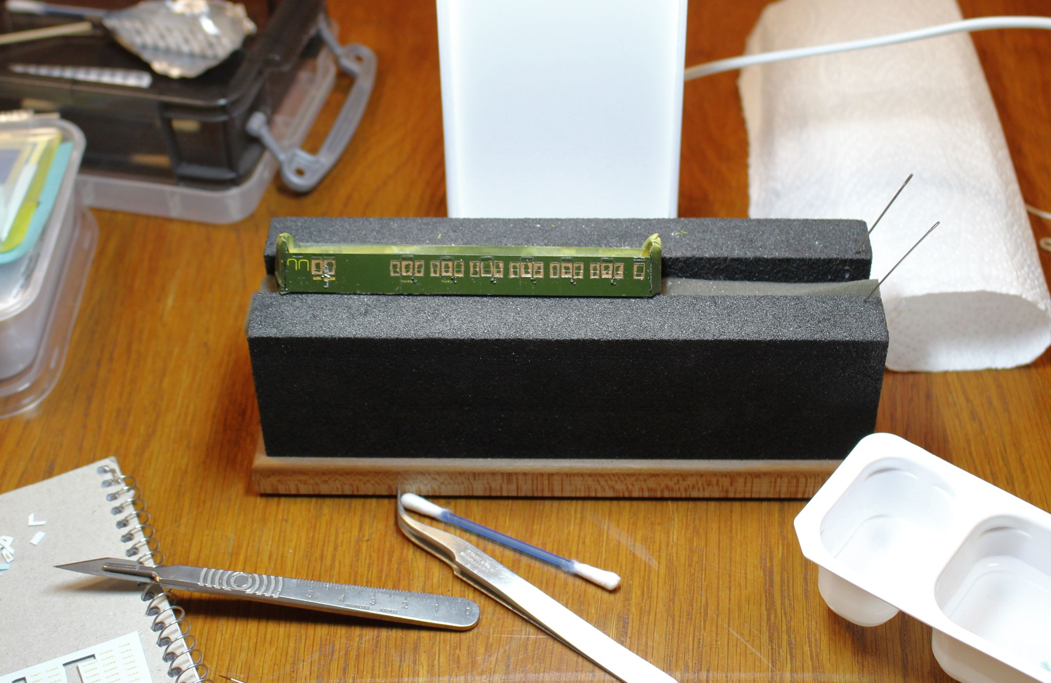
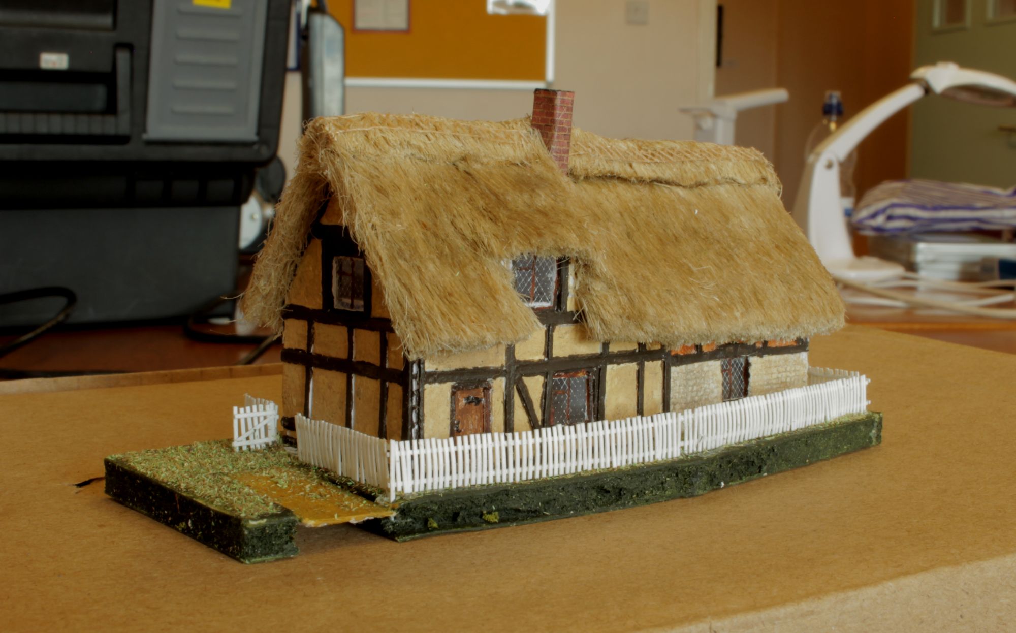
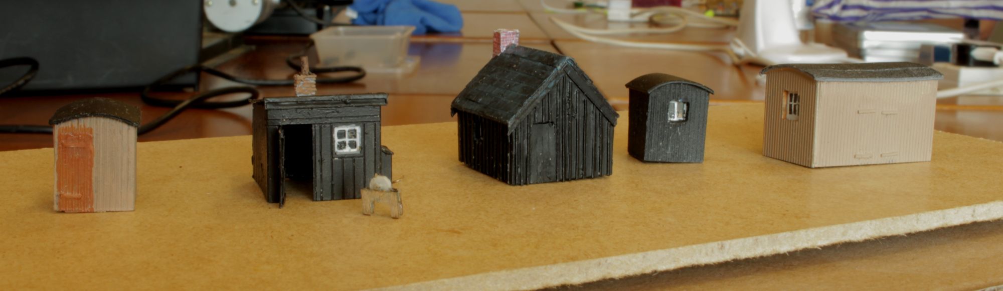
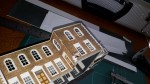
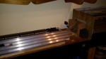
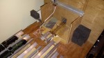
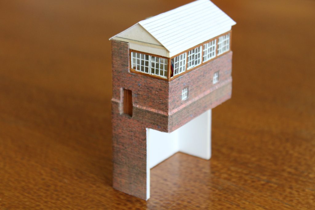
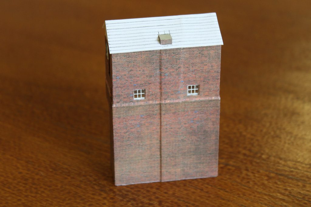
Nigel has been busy with Drws y Nant and had the signal box with him ostensibly to make some slates. However the general chat meant no progress was made there.
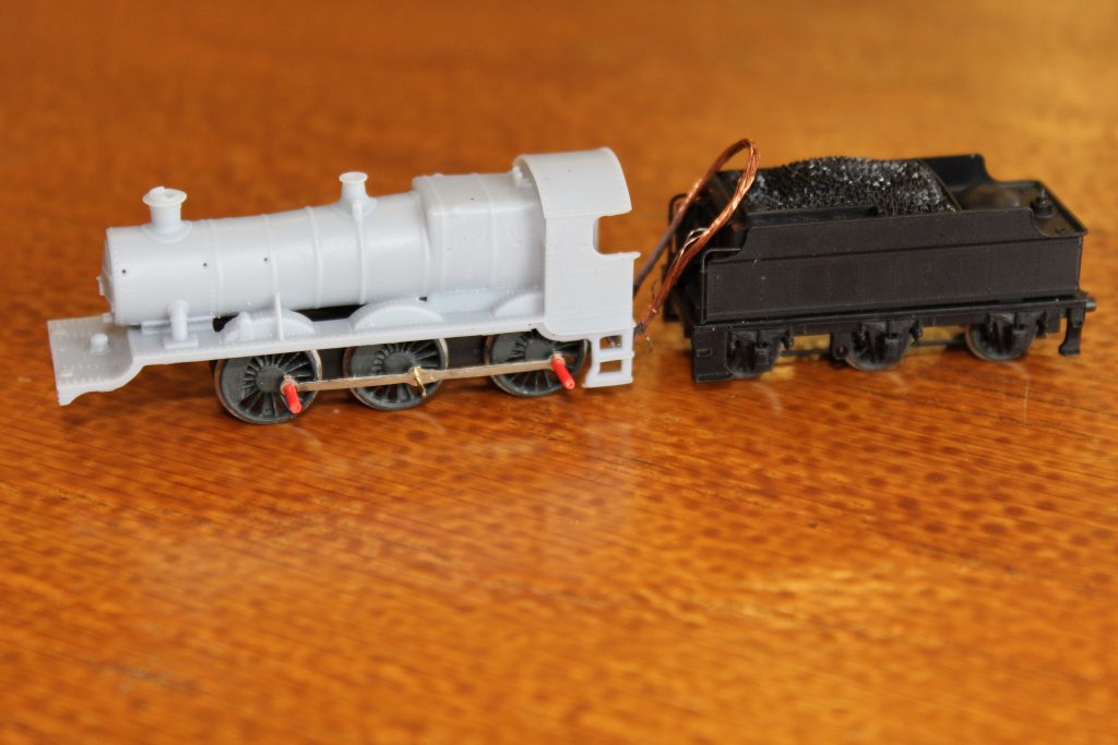
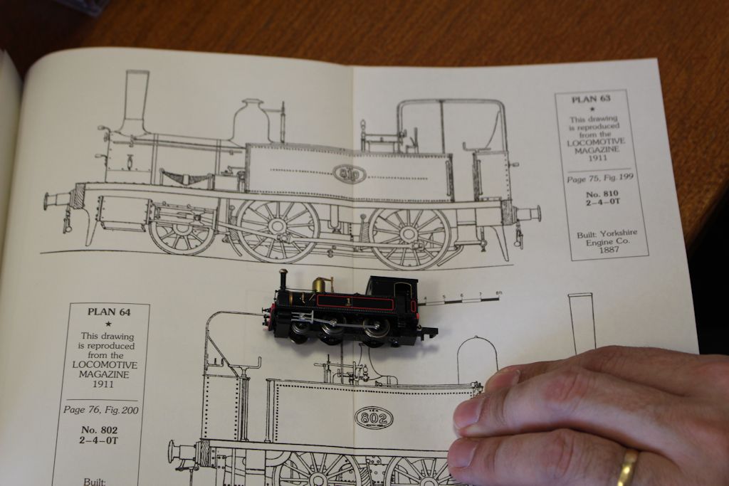
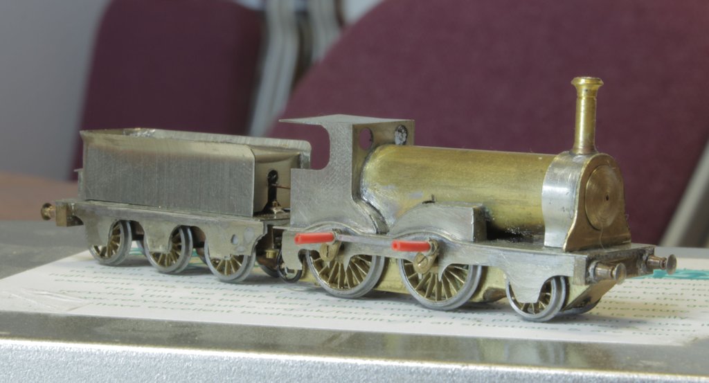
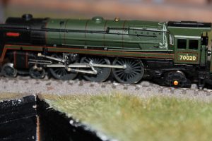
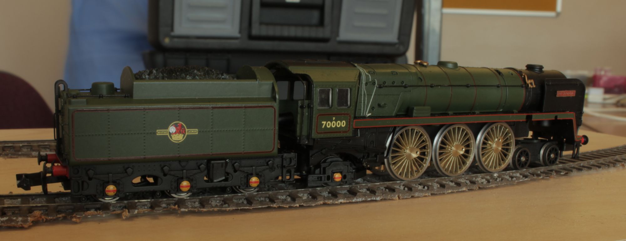
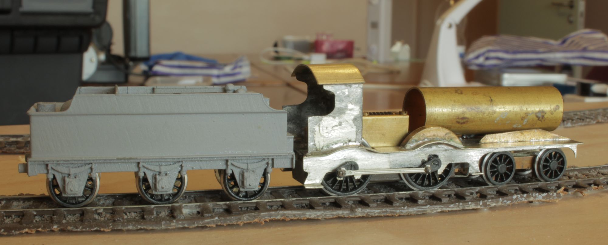
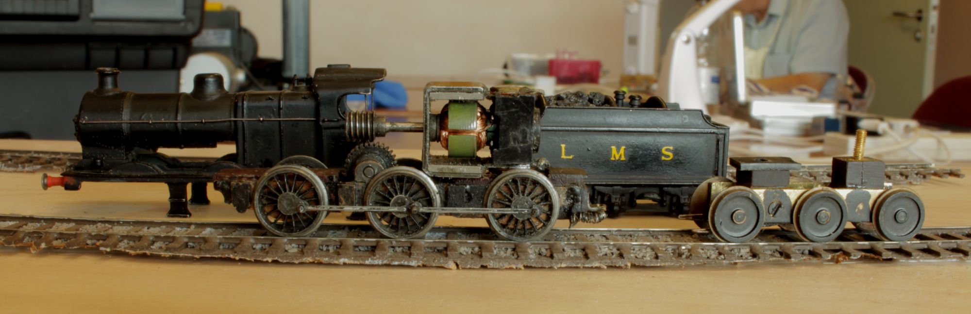
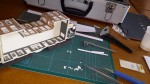
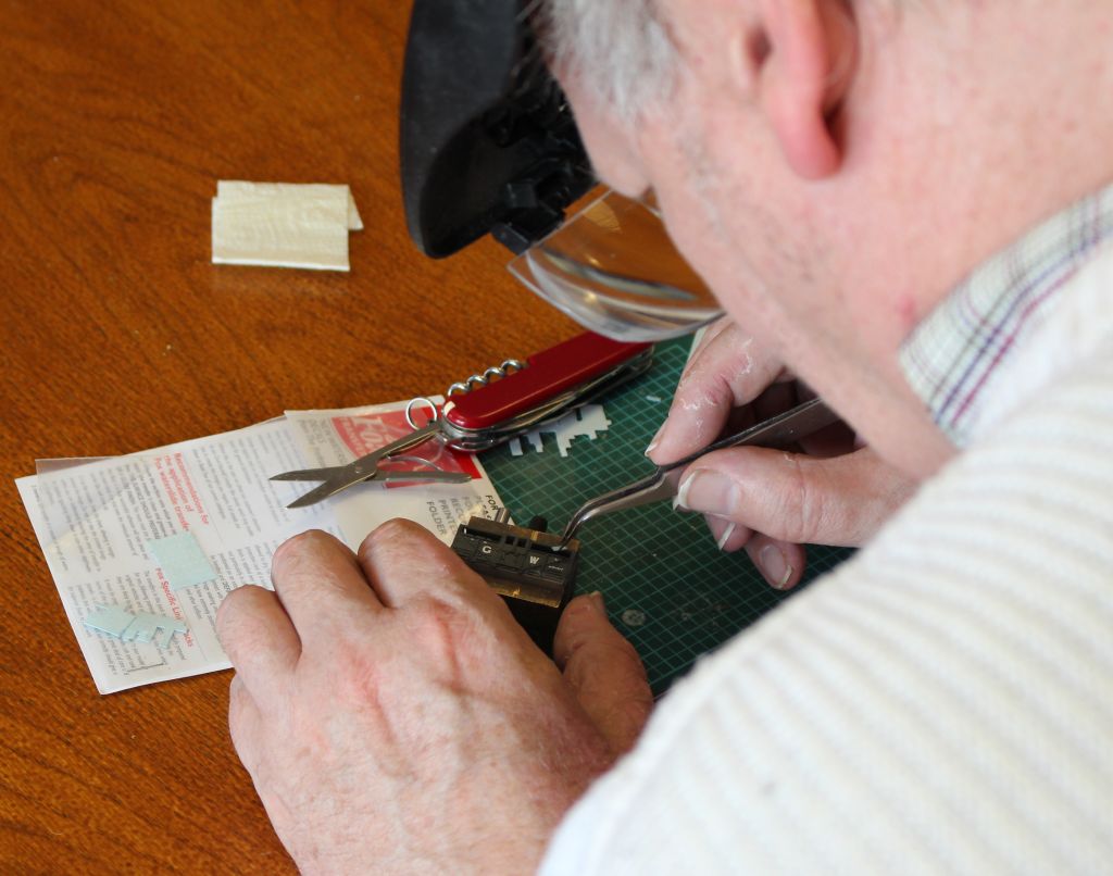
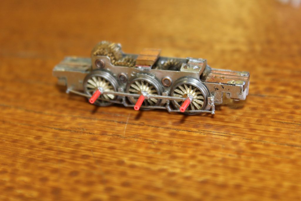
The GWR Mogul is a 3D print from Atso Cad on top of one of the Association milled brass Manor chassis. Compare this to the scratch built version from a few years ago and it is a lot crisper. At least the running qualities will be predictable.
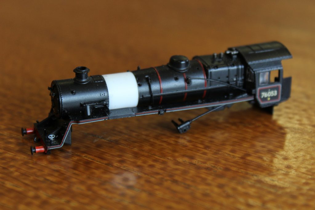
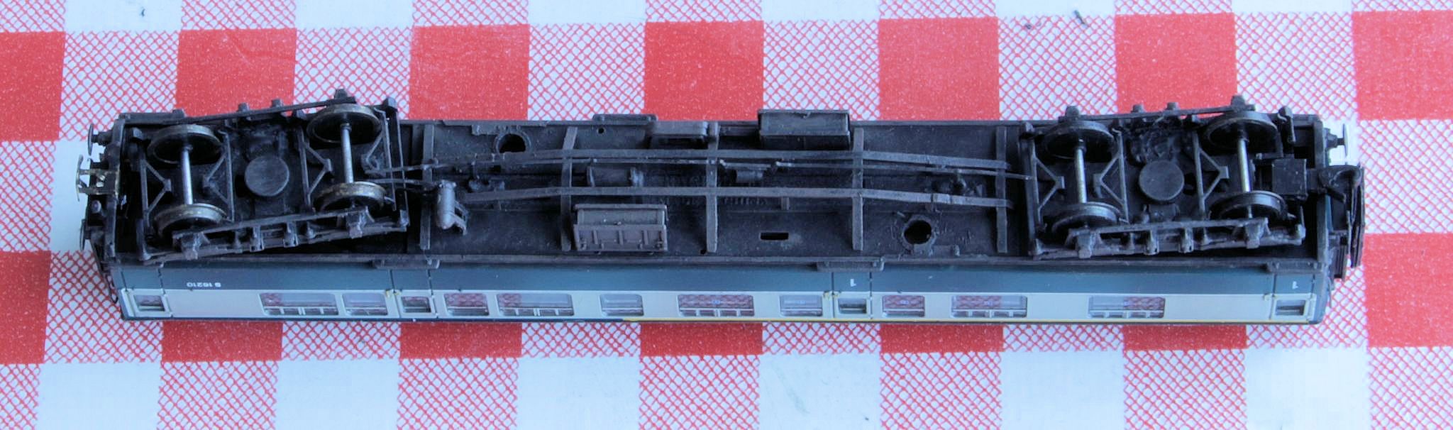
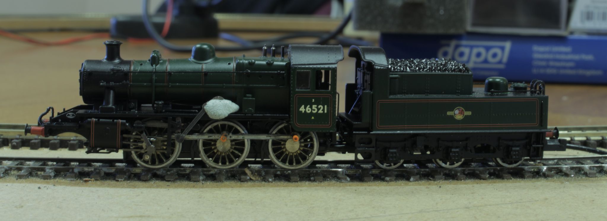
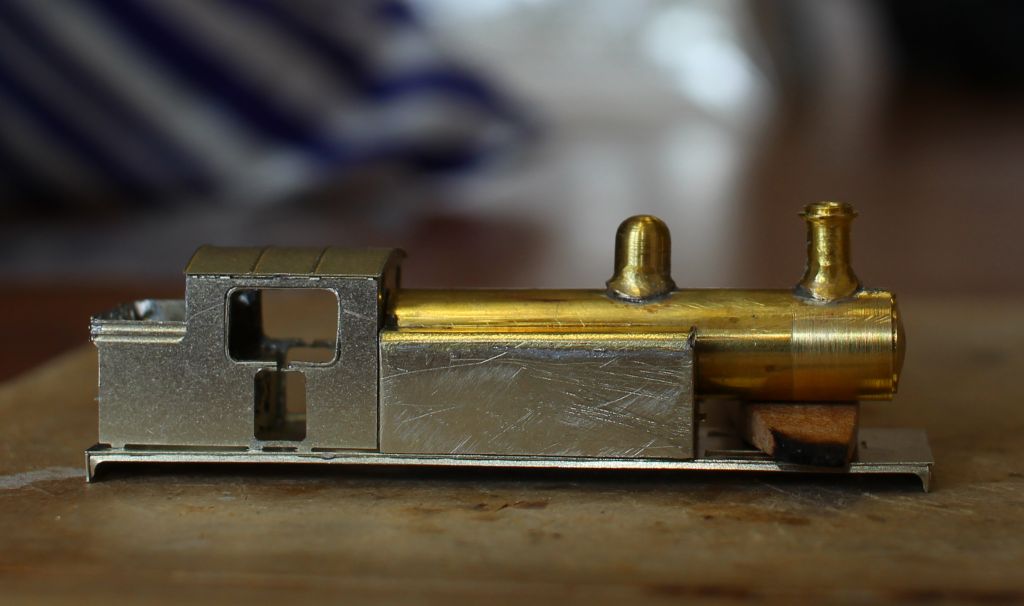
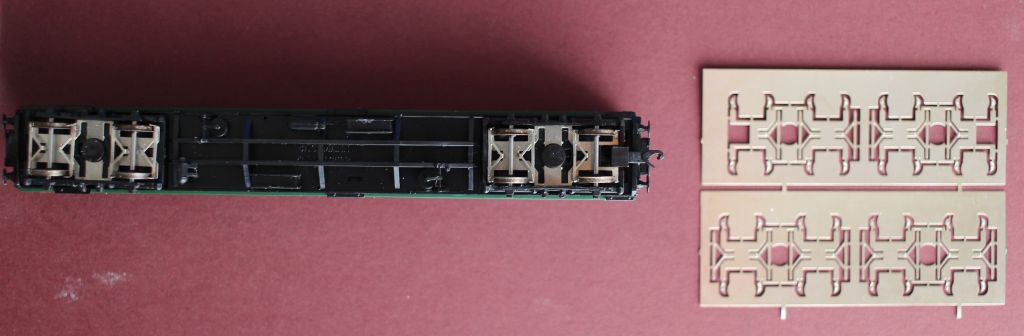
Also photographed was a cut and stretched 4MT 4-6-0 body created from a spare 2-6-0 item which Gareth donated to Nigel a while ago. Counter trades this month included some Farish spoke Wagon wheels.
All in all a successful session with lots of ideas exchanged and plenty of room to stay safe.